Wide application hard drives as devices for long-term storage of information began after the release by Shugart Technology (now Seagate Technology, Inc.) of the ST506 5.25-inch disk. The device with a capacity of 5 MB used the ST506 interface board, developed in the late 70s by Western Digital, to connect to the computer. To connect the hard drive to the interface board, a 34-wire flat cable was used, to which two devices could be connected. In order for the disks to be addressed, part of the cable was twisted (similar to the cable for connecting disk drives). In addition, a separate 20-wire flat cable was used to communicate with each of the drives. A major drawback of the ST506 interface was the incremental movement of the heads (one step per move instruction), as is still the case in floppy drives. A newer model - ST412 - provided the possibility of buffered seek, which allows one command to move the heads several steps (for example, across the entire disk).
Point out two that will stand out over the next few years in the storage market. Despite the appearance a large number cloud storage services, the demand for on-premise, high-bandwidth solutions continues to increase due to the greater amount of data that needs to be stored.
In this scenario, old hard drives, improved over the years, is still the reference solution on servers, workstations, and personal computers on the desktop as a means of mass storage. It is erased every time the computer is restarted, which is why hard drives are sometimes referred to as mass storage.
The main advantage of hard drives with ST506/ST412 interface is their low cost. Almost all the electronics responsible for the operation of the disk was located on the interface board. The signals controlling the drive of the heads were transmitted over a 34-wire cable common for two devices connected to the controller, and data exchange with the controller was carried out via 20-wire flat cables directly in the form of a sequence of pulses read from the disk or written to it. The connectors used for connection are described in Appendix 3.
The hard drive is connected to the motherboard using a controller hard drive, which in turn acts as an interface between the processor and hard drive. The hard disk controller manages standard disks, interprets commands sent by the processor, and sends them to the appropriate disk. Hard drives are usually grouped by interface as follows.
These tracks are divided into zones, called sectors, which contain data. The term "cylinder" refers to all data found on the same track of different dishes, as this represents a "cylinder" of data. Finally, the term "clusters" refers to the minimum area a file can occupy on a hard drive. The operating system uses blocks, which are actually groups of sectors. A small file can span several sectors.
The small set of ST506/412 interface commands made it difficult to create high-capacity drives. Almost all drives with this interface had a rotation speed of 3600 rpm.
The ST506 interface supports two modulation methods for data recording and playback: MFM (Modified Frequency Modulation - modified frequency modulation) and RLL (Run Length Limited - coding with a limitation on the length of the recording field).
Lock mode and 32-bit transfer are used to get the best performance from your hard drive. Blocking mode involves transferring data in blocks, typically in 512-byte packets, which prevents the processor from processing large numbers of one-bit minute packets. Thus, the processor has the "necessary time" to perform other operations. Unfortunately, this method of data transfer is only useful for older operating systems, since current operating systems use their own hard drive manager, which makes this administration system obsolete.
MFM Modulation
MFM is a type of conventional frequency modulation widely used in broadcasting and communications. The difference lies in the fact that the modified modulation makes it possible to provide a twofold increase in data recording density due to the fact that not all synchronization signals are recorded on the disk and the value of the previous bit is taken into account when recording each bit. For one transition (change of direction) of magnetization, one to three bits of data can be recorded). Signals from the head are transmitted over the data cable in analog form; data is separated from the synchronization signals using a special device - a separator installed on the controller board.
If you don't know this, there are several solutions at your disposal.
- Check the documentation on your hard drive.
- Check specifications your disk on the Internet.
- Run tests to determine it.
The main advantage of MFM modulation is the simple binary form of the signal written to disk. When writing to a track, 17 sectors of 512 bytes each were used. The theoretical transfer rate limit with drives using MFM is about 4Mbps
(17sectors*512bytes/sector*8bits*3600rpm): 60s = 4177920 bps.
However, the real exchange rate is several times lower, since for such disks the Interleave factor is not equal to 1. This was due to the fact that the controller did not have time to process the read data before the head moved to the next sector. With an interleaving factor of 1:1, the order of sectors on a track is natural: 1, 2, 3,...16, 17. With an interleaving factor of 3:1, the sectors on the disk have the following order: 1, 7, 13, 2,... , 11, 17. The first number in the interleave ratio indicates the number of disk revolutions required to completely read or write one track. Due to write caching, it was possible to set a 1:1 striping factor for ST506 disks.
When switching from 16-bit to 32-bit mode, the performance improvements are almost minimal. In any case, in theory, it is no longer possible to select a mode, because the motherboard automatically determines the mode that should be used depending on hard type disk.
In this case, the transfer rate will be lower than that declared by the manufacturer. Data transfer rate: The amount of data that can be read from or written to a disk per unit of time. The faster the disk spins, the higher the transfer rate. And vice versa, HDD, which spins fast, tends to get louder and warmer. Latency: The amount of time between the time the disc is on the track and the time the data is there. Access. The average time it takes the spindle to find the correct track and access the data. In other words, it represents the average time it takes to provide data after receiving an order to do so. The cache is used to store disk data that is accessed more often, looking in this way, improving overall performance. Interface: refers to the connections used by the hard drive. Main interfaces of hard disk are.
- Capacity: The amount of data that can be stored on the hard drive.
- It is expressed in bits per second.
- Rotation speed: the rotation speed of the plates.
- It is expressed in revolutions per minute.
Many of you probably haven't forgotten the Norton Utilities Calibrate program, which optimizes disk performance by selecting the striping factor that best matches the speed of your disk and controller.
RLL modulation
Another modulation method (2.7 RLL or simply RLL), proposed by IBM in 1986, uses recoding of the original information with the introduction of redundancy. The RLL method converts data into 16-bit words that allow recording from 2 to 7 bits of the disk magnetization state in one transition (these numbers are included in the name of the method). The use of RLL modulation places higher demands on the quality of the disk surface and the uniformity of its rotation. In addition, read-write channel amplifiers should have slightly different characteristics compared to MFM modulation. Hard drives with an ST506/412 interface that use the RLL method, as a rule, have an R suffix in their designation (for example, ST157R). 26 sectors of 512 bytes can be written to one track of the disk, which gives the theoretical possibility of exchanging at a speed of (512 * 26 * 8 * 3600): 60 = 6489760 bps.
Among the various types of components specifically designed for servers, the storage section is worth mentioning. The storage system is one of the main pillars for a server, since one of the main functions of any server will be to store the data that it receives from other computers or users located in it. Depending on the type of data that is stored and the traffic required to support this server, it will be convenient to select a specific disk type.
Obviously, you won't need the same bandwidth and data access speed on an internal server where you store family files or your private email server as you would on a company server with 500 users connecting at the same time.
The RLL method was subsequently developed to the ability to write from 3 to 9 bits per magnetization transition (3.9 RLL, ARLL, ERLL), which made it possible to record 31 sectors on a track and provided a theoretical limit for the exchange rate with a disk of 7618560 bps.
RLL disks can be safely connected to MFM controllers (albeit with loss of capacity), while the reverse operation is generally incorrect. Many probably remember this method of "increasing" the size of the disk, practiced a few years ago - but it does not provide sufficient reliability for data storage.
Therefore, it is important to distinguish between the storage system and the connection interface for these storage systems. This is one of the storage connection interfaces known to be most commonly used in home storage systems, and is the most common in motherboards personal computers and laptops as it offers very balanced performance for this type of platform.
However, the mere fact of including one of the two interfaces already determines the characteristics and performance of this storage unit. Talking in terms of better or worse is not the right thing to do when it comes to connectivity interfaces, as that would be like comparing Formula 1 to an SUV. Formula 1 has no competitor in circuits, but there is no point in them, while an SUV will not perform well in circuits, but you can use it on any terrain.
Today, ST506/412 drives are found only in very old computers.
ESDI
As the speed of computers grew, the ST506 interface ceased to meet all the requirements and in 1985 a new standard was developed - ESDI, which, in fact, was a simple extension of the capabilities of its predecessor. The cables used in the ESDI specification do not differ externally from the ST506 cables, but the signals are transmitted through them differently (see Appendix 3). If you, using the similarity of cables, connect (by mistake or on purpose) the ST506/412 hard drive to the ESDI controller (or vice versa), the results can be the most deplorable. The cables used in the ESDI interface could be up to 9 feet (3 meters) long, and the signals were transmitted mostly in-phase (with a common ground), with the exception of data and synchronization, which were transmitted using a differential method. Data was transmitted over the serial line in chunks of 16 bits, followed by a parity bit. It was also possible to confirm the transmission of data.
This article aims to list several models of hard drives made by the industry's most famous companies. In this list, we have tried to indicate the main characteristics that will be checked upon purchase. new hard disk. The following list shows new hard drives that were sold on their respective manufacturer's websites at the time of the survey, i.e. these hard drives are state of the art, which may make their prices not so low.
Prices were searched online, so some were found in dollars or pounds, which may represent a difference between the price shown here and what you would find in a computer store. Another detail to mention is that possible freight rates have not been included in the price as they can vary greatly depending on the region you live in.
The separator, in accordance with the new specification, was installed directly on the hard drive board, and not analog signals were transmitted over the data cable, but real data in digital form, which made it possible to select the separator parameters for a specific type of device, since signal distortion in the cable no longer mattered. This method increased the reliability of data transmission and increased the exchange rate with the controller up to 10 Mbit / s due to the transmission of digital signals over the cable. In addition, the ESDI interface provided the ability to use high-capacity hard drives and optical drives.
Search features. Perhaps when you go directly to the list, you don't really understand what it represents, so we'll give you a few quick explanations about each item that appears in it. "Rotation Speed" indicates how many revolutions per minute the hard drive is capable of running. The higher the number of revolutions, the faster the data stored on the hard disk will be read. Already "power" indicates from which source the specified device captures the electrical energy necessary for operation.
"Interface" indicates the type of technology used to transfer data between a computer and mass storage devices. This type of interface was used as the standard for a long time, but the demand for higher speeds grew and they were eventually replaced by the serial interface.
The ESDI interface provided three device selection signals, which allowed up to 7 drives to be connected to it. Head select signals allowed up to 16 heads to be directly addressed, however a special Select Head Group command allowed up to 256 heads (16 groups of 16 heads each).
SCSI
The original SCSI (Small Computer System Interface) interface was proposed in the late 70s by Shugart Associates under the name SASI (Shugart Associates System Interface) to replace IBM's IPI (Intelligent Peripheral Interface) system bus. After failing to compete with IBM, this interface was proposed to the ANSI X3T9.2 committee as a lower-level interface called SCSI. In 1984, this committee completed the development of the SCSI-1 specification and in 1986 it was published in its final form. This interface provided the connection of a wide class of peripheral devices, such as hard drives, printers, scanners, streamers, CD-ROM drives, etc. SCSI is a system-level interface, not a device-level one. Unlike the ST506/412 and other serial device interfaces, SCSI transmits data bits in parallel, which provides a significant increase in the speed of communication between the device and the host adapter.
After a few explanations, we finally get to the list! List at least 3 types of buses. Which bus was designed specifically for video adapters and is found on some computers today? Which bus is available in multiple segment types, each with a speed and a different physical size?
List 3 types of storage units. Is data storage hard drives using some physical function? Did the term Winchester denote a type of storage? What are the three types of HDD communication interface? Which hard drive interface uses serial data?
The SCSI interface is used not only in IBM-compatible computers, but also in the Macintosh, SPARC, VAX, etc. families. One of the reasons for such a wide distribution of the SCSI interface is that it does not impose any restrictions on communication between the controller and the peripheral device. The SCSI bus can be used to connect a computer to multiple peripheral devices (both external and internal). Moreover, the sharing of one peripheral device by several computers connected to a common SCSI bus is allowed (although this is much more difficult to do than to write, but this is a separate discussion). Devices connected to the SCSI bus can play the role of master (Initiator) or slave (Target), while the same device can be a slave in some cases and a master in others. This division of device functions allows you to organize the transfer of data from one peripheral device to another (for example, backing up data from a hard drive to a streamer cassette). The exchange between devices on the SCSI bus occurs in accordance with the high-level protocol and addressing is carried out at the level of logical, not physical (as in ESDI) blocks. Programs for working with SCSI devices do not use physical characteristics specific device(number of heads, cylinders, etc.), but deal with logical blocks, which makes it possible to work with virtually all block devices.
Give two advantages and two disadvantages of solid state drives. Give the advantage of optical drives and disks over magnetic disks. What is the speed limit of the serial communication interface? Which front end connection is used specifically to connect to the keyboard and mouse?
Which external communication interface is an adaptation of the internal communication interface and allows you to connect devices at high speed? It initializes the video, shows a settings frame containing a list of the machine's hardware configuration. What is disk partitioning?
SCSI devices are connected using a cable (usually flat) with 50-pin connectors (Appendix 3). Both in-phase and differential (using "current loop") data transmission over the cable are possible; with common-mode transmission, the cable length can reach 6m, with differential transmission - 25m. For guaranteed transmission of signals over the SCSI bus, the line must be terminated using terminators (a set of resistors) installed at both ends of the SCSI bus.
What types of partitions and how many of each type can exist on a disk? In fact, an extended partition is nothing more than a primary partition that is used to store logical partitions. Section Logic: These are sections that are "inside" extended sections. Each extended partition can have up to 255 logical partitions.
What are the types of disk formatting and how do each type work? List at least 3 types file systems. Specifications external hard the disk you choose will be the result of the use you make of it. This guide is intended to provide you with the keys to making your choice in the best possible conditions.
The SCSI specification calls for up to eight devices to be connected to the bus, but given that each device can contain 8 logical blocks, and each block can contain 256 subblocks, the expansion possibilities are virtually unlimited. Each device connected to the SCSI bus has its own identifier, which is set using jumpers or switches directly in the device. Identifiers allow you to address devices and set their priority (the larger the value of the identifier, the higher the priority of the device).
The interface is an intermediary through which data and commands flow between the external hard drive and the computer. Here are the main current interfaces. You will be able to use them and share your information with different computers in your local network. Their use is simple, however has an average performance for? . External hard The drive can be equipped with various options such as.
Data encryption software Rubber protection system, solid shell or spring-loaded button Reserve copy, external display to display data. network port, to connect the drive to the network and therefore share your data with that. Then access to the external hard drive becomes available through a simple Internet connection. Now you're securely put on external rigid rims: choose our flagship brands.
Over the past years, the SCSI interface has been significantly expanded - the Fast-SCSI and Wide-SCSI specifications have appeared, providing faster data exchange with SCSI devices. Currently, the SCSI interface is used mainly in high-performance systems intended for collective use (file server disks, scanners, etc.).
ATA
The IDE/ATA specification was proposed as an inexpensive alternative to the ESDI and SCSI interfaces for the IBM PC XT/AT family of personal computers. As a result of cooperation between Western Digital and Compaq Computer Corporation, the IDE (Integrated Drive Electronics) interface, also called ATA (AT attachment), was developed. The first industrial devices based on IDE/ATA were released in 1986. The interface was standardized (ANSI X3T9.2/90-143) in 1990. like ATA (AT Attachment). The main difference of the new interface was the implementation of most controller functions directly on the disk drive board. This approach simplified and reduced the cost of host adapters used to connect hard drives to a computer, and made it possible to ensure a high level of compatibility between devices from different manufacturers.
The input/output addresses used by the IDE devices are the same as the ST506/412 addresses, but the controller functions have been transferred to the control board for the disk drive and hard drive heads. Information about the disk geometry (the number of heads, cylinders and sectors) is stored in the device itself. Often, the logical parameters of a disk are transferred to the BIOS that do not match its physical parameters, i.e. translation is used, which allows you to install hard drives in computers with old BIOSes that do not provide the ability to arbitrarily set device parameters (in most modern BIOS implementations, this feature is supported as type 47 - User Defined).
The basic set of IDE interface commands fully corresponded to the command set of the Western Digital WD1002/1003 controller, which was used in the IBM PC AT computer. When standardizing the IDE interface, the same number was added to the 12 basic commands. The transfer of most controller functions to the control board allows you to slightly increase the speed of data exchange with the disk. Usually IDE drives have a small built-in cache memory (up to 256Kb) and allow you to work with a 1:1 interleaving factor (a track can be read entirely in one disk revolution).
The host adapter for connecting IDE drives is often installed on system board(Mother board) or combined with a disk drive controller and I / O ports (serial and parallel) on a special board inserted into the expansion slot (a multicard, as it is often called). Devices are connected to the host adapter using a 40-wire flat cable (see Appendix 3), to which two hard drives can be attached. For correct addressing of devices, one of the hard drives must be set to Master (master) mode, the other to Slave (slave) mode. The disk operation mode is set using jumpers, usually located near the hard drive signal connector.
Figure 2. Jumpers for setting Master/Slave mode
Comparison of disk interfaces
The table shows the comparative characteristics of the various interfaces used to connect disk devices. ST506/412 and ESDI interfaces modern computers are practically no longer used; information about them is provided only to compare their capabilities with SCSI and IDE.
Table 1.
| Parameter | ST506/412 MFM | ST506/412RLL | ESDI | SCSI | IDE/ATA |
| Maximum exchange rate | 5Mbps | 7.5Mbps | 10/24Mbps | 24/40MB/s | 10MB/sec |
| Maximum number of devices | 4 | 4 | 7 | 56 | 2 |
| Maximum number of devices in DOS | 2 | 2 | 2 | 36 | 2 |
| Connecting other devices | - | - | - | + | - |
| Number of sectors per track | 17 | 26 | 32-36 | Undefined | Undefined | All I/O operations are performed using the processor | Partial use |
| Multitasking I/O | - | + | + - [Modern IDE/ATA extensions support multitasking I/O] | ||
| Automatic error correction | - | - | + | + | + |
| Low level formatting | + | + | + | - | - |
The prices and parameters of hard drives have long been equal. The main thing is that the hard drive does not fail without the possibility of recovery. Hard drives are not reliable. Instead, they have a warranty card) Regardless of the manufacturer, from a batch of 1000 drives, from 1 to 10 hard drives are returned long before the warranty period expires, even if they are positioned as server models. From time to time, all manufacturers have unsuccessful models. In addition, the source of failures is often off-disk.
Another important parameter is the spindle speed. Usually it is 7200 rpm, but now many manufacturers reduce it to 5400 in order to reduce power consumption, noise and vibration. By the way, despite the fact that usually the main noise is produced by piles of fans located in system block, the hard drive can also be quite noisy, especially under load. So the last parameters are also important. Of course, you have to pay for the low temperature during operation and noise reduction. For example, there will be a high access time. This means that if you write an OS to this disk and run several programs from it, then you are unlikely to get a decent speed for their work. Or there will be low speed. In 2013, the largest manufacturer Seagate refused to produce 2.5" hard drives with a speed of 5400.
Note ! Do not forget that each hard drive has a cache memory, which also affects performance. The average volume for Terabyte drives today is 32 MB (16 MB is very small), but you can also find models with a 64 MB cache,
If the disc is noisy, then either it was made earlier than 1999 (ancient), or it was dropped!
The most harmful moments for the screw are its start-up and stop. At this time, the mechanical part wears out very much. Increases the likelihood of accidental damage to the surface. In general, it is believed that a screw that spins without stopping lives much longer.
IDE
IDE - parallel interface for connecting drives ( hard drives and optical drives) to your computer. Developed in 1986 by Western Digital, it later became known as ATA, then PATA.
An outdated interface for connecting hard drives, both morally and physically, now not used in computers.
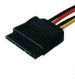
SATA
SATA (Serial ATA) is a serial interface for data exchange with information storage devices. SATA is an evolution of the parallel ATA interface (IDE), which was renamed PATA (Parallel ATA) after the advent of SATA.

SATA 1 (up to 1.5 Gb/s)
Originally, the SATA standard called for a 1.5 GHz bus, providing approximately 1.2 Gb/s (150 MB/s) throughput. (The 20% performance loss is due to the use of the 8B/10B coding system, where there are 2 service bits for every 8 bits of useful information). The throughput of SATA/150 is slightly higher than that of the Ultra ATA (UDMA/133) bus. The main advantage of SATA over PATA is the use of a serial bus instead of a parallel one. Despite the fact that the serial method of exchange is fundamentally slower than the parallel one, in this case this is compensated by the possibility of operating at higher frequencies due to the lack of the need to synchronize channels and the greater noise immunity of the cable. This is achieved by using a fundamentally different method of data transmission (see LVDS).
SATA 2(up to 3 Gbps)
The SATA/300 standard operates at 3 GHz and provides up to 2.4 Gb/s (300 MB/s) throughput. It was first implemented in the nForce 4 chipset controller from NVIDIA. The SATA/300 standard is often referred to as SATA II or SATA 2.0. Theoretically, SATA/150 and SATA/300 devices should be compatible (both a SATA/300 controller with a SATA/150 device and a SATA/150 controller with a SATA/300 device) due to support for speed matching (down), however, for some devices and controllers require manual setting of the operating mode (for example, on Seagate hard drives that support SATA/300, a special jumper is provided to force SATA/150 mode on).

SATA 3(up to 6 Gbps)
The SATA Revision 3.0 specification was introduced in July 2008 and provides for the ability to transfer data at speeds up to 6 Gb / s (600 Mb / s for data with 10b / 8b encoding). SATA 3.0's improvements over the previous version of the specification include improved power management in addition to faster speeds. Compatibility is also preserved, both at the level of SATA connectors and cables, and at the level of exchange protocols.
SATA Revision 3.1
Innovations:
- mSATA, SATA for SSD drives in mobile devices, PCI Express Mini Card-like connector that is electrically incompatible
- Zero-power optical drive. In standby optical drive SATA does not consume power
- Queued TRIM Command improves SSD performance
- Required Link Power Management reduces overall system power consumption of multiple SATA devices
- Hardware Control Features allows host identification of device capabilities
SATA Revision 3.2 - SATA Express
- SATA Express is software compatible with SATA, but uses PCI Express as the carrier interface. Structurally, it consists of two SATA ports located side by side, which allows you to use them as drives with SATA interface, and directly drives that natively support SATA Express. The data transfer rate in this case reaches 8 Gb / s if one connector is used and 16 Gb / s if both SATA Express connectors are used.
- µSSD (micro SSD) - is a BGA interface for connecting miniature, built-in drives.
AHCI, or how to take advantage of Serial ATA
You have bought a new hard drive with Serial ATA interface. And, of course, we heard a lot about the new interesting feature implemented in the latest models - NCQ. Looking forward to a noticeable increase in speed Windows boot and programs, as well as reducing the noise of the hard drive, you connect the hard drive, install the operating system and ... Now you need to do additional manipulations to enable AHCI support and install suitable drivers. Otherwise, NCQ technology, as well as other interesting features, will remain unused. The idea underlying the NCQ (Native Command Queuing) technology has already been implemented more than once in hard drives and controllers, but not in those used in ordinary personal computers.
- So, this is the principle behind NCQ. As you know, the hard drive is quite slow compared to other PC devices due to its mechanical nature. Especially a lot of time is spent on moving the heads between the tracks, on which the data sectors requested by the system are located. To minimize these movements, you can use the well-known computer science method of reordering the command queue. In this case, the distance between the tracks to be accessed is used as the rebuilding criterion. Read commands coming to the hard disk from the system are not executed in order, but are accumulated in a queue. There they are interchanged in such a way that the head moves as little as possible when executing adjacent requests. Due to this, acceleration is achieved. Not all requests will complete faster - some may get "stuck" in the queue, skipping other requests. And the appearance of a write request generally complicates the processing of the command queue, since a situation of data integrity violation is possible.
In addition, such a technology will only be beneficial if the commands to the hard drive are received in a dense stream and much faster than it has time to execute them. In the conditions of modern PCs, this situation does not occur very often - mainly at the time of loading the OS and large software packages. Therefore, the implementation of NCQ technology has only recently been taken up, although in a server environment, intelligent reordering of commands has been used for a long time and successfully.
AHCI protocol
The Serial ATA controller, according to the requirements of this standard, must support at least 2 modes of operation. The first is the standard ATA controller emulation mode. In this mode, the controller completely repeats the PATA hard disk access protocol and, from the point of view of the operating system and drivers, does not differ from the PATA controller. At the same time, the hard drives connected to it are emulated either as Master devices on a separate channel, or, if the OS “does not understand” more than two channels, as a pair of Master and Slave devices. This mode is enabled by default and is fully supported by all operating systems and BIOSes.
The problem is that in the emulation mode, the implementation of additional Serial ATA functions is partially or completely impossible, otherwise compatibility with the classic ATA implementation will be violated. Therefore, the controller has the ability to switch to the "native" (Native) Serial ATA mode.
The AHCI (Advanced Host Controller Interface) protocol just describes the behavior of the controller in Native mode from the point of view of the system. It describes how the controller handles the command queue, where and how they are stored, how the programmer should place commands in the queue, and where to get the results of their execution. All the conventions of the ATA protocol are discarded, all the difficulties with manipulating registers and flags are abolished as unnecessary. The implementation of all additional Serial ATA features, including NCQ, Hot Swap, Port Multiplier, Staggered Spin-Up, etc., is now unlimited.
AHCI is an addition to the SATA standard, which, in general, does not describe the requirements for host controllers (controllers on the side of the computer system to which the hard drive is connected). Together with AHCI, the Serial ATA standard is a complete solution for organizing a disk subsystem in a new generation of PCs.
However, compatibility with software, which does not natively support Serial ATA. The controller cannot work in two modes at the same time. By switching to Native mode, it loses the ability to accept commands from software that does not "understand" the AHCI protocol.
Such software, oddly enough (or not surprisingly), is the operating Windows system. As the developers of this operating system admit in a special document (www.microsoft.com/whdc/device...alATA_FAQ.mspx), the disk subsystem of all Windows versions pre-Vista versions will not support AHCI. They explain this by the presence of features in the implementation of AHCI by manufacturers of different controllers. In the future, the Windows kernel will implement a new mechanism for connecting drivers - Ataport, and the drivers will include a standard miniport for the Native mode of the Serial ATA controller.
We owners of new operating systems of the Windows family can already easily enjoy such benefits of increased productivity. Currently latest versions Windows OS is installed well without third-party drivers, which has a beneficial effect not only on the company's image, but also on convenience for the average user.