Device hard drive
A hard disk drive consists of one or more plates with a magnetic layer, heads, a positioning device, a housing, and a controller. plates- the main element of the drive, information is placed on them. heads designed to read and write information to the plates. Positioning device provides movement of heads to the necessary place on a surface of plates. Frame serves to fasten the remaining structural elements, as well as to protect the plates and heads from mechanical damage and dust. Controller controls all electrical and electromechanical components of the drive and provides information transfer from the computer and vice versa.
fig.1
HDD Geometry
plates drives are made of metal or glass and have a magnetic layer on one or both sides, on which information is recorded. The side of the plate with the applied magnetic layer is called the working surface. surfaces plates are carefully polished and coated with a ferromagnetic layer. The coating material and the number of layers (the magnetic layer may consist of several layers of different materials) may be different for different drives. There is one for each work surface. head(in fact, modern drives use separate write and read heads made using different technologies to increase the recording density). The surface of the plate is divided into thin concentric annular zones called tracks. And each track, in turn, is divided into several sections, called sectors. Sector can be conditionally divided into two areas: the data area and the service information area. Service information is written to the plate once at the factory and is not subject to change in the future. The service area includes a unique sector address in the drive, by which the controller identifies it when writing or reading information. The data area contains useful information written to the drive. This area can be changed many times during operation. The volume of the data area somewhat exceeds the information capacity of the sector due to additional information - for verification and, possibly, error correction. The sector data area can only be updated in its entirety. Those. one or ten bytes cannot be written to the drive - only the entire sector. All heads move synchronously and this process takes some time. The set of tracks on different platters available at the same time with the head position unchanged is called cylinder. From the point of view of the performance of the disk system, it is advisable to place sequential data within the same cylinder.

fig.2
In older drives, all tracks contained the same number of sectors. In this case, the unique address of each sector (i.e., the minimum piece of information stored on the drive) could be given by three numbers: cylinder, head, and sector numbers. Thus, a three-dimensional coordinate system was introduced on the hard disk, very reminiscent of a cylindrical one in three-dimensional space: the cylinder number corresponds to the radius, the head number corresponds to the height, and the sector number corresponds to the angle.
If we represent such a construction in a Cartesian coordinate system (for example, consider that our "disk" is assembled from several boards with flash memory), then it will be a parallelepiped in shape, divided into cells - sectors.
However, with such a layout of the hard disk, the recording density on the outer tracks turns out to be approximately three times lower than on the inner ones (the same amount of information per three times the track length). Therefore, modern drives use the so-called zone recording, in which the surface of the plates is divided along the radius into several zones (usually about a dozen), in each of which the number of sectors per track is constant, however, this number varies from zone to zone. The outer tracks contain more sectors than the inner tracks. This allows you to approximately double the information capacity of the drive without changing the maximum recording density. But, being represented in Cartesian geometry, such a figure will have a rather complex shape that the BIOS cannot work with. Therefore, from the whole variety of interfaces hard drives(ST506 / 412, ESDI, IDE, SCSI) only the last two remained, which are distinguished by the greatest "intelligence", which is expressed in the ability to carry out such a "coordinate transformation" in which an irregularly shaped figure turns into a neat "brick". At the same time, such a conversion allows you to bypass or, at least, slightly mitigate the restrictions imposed by the BIOS on the maximum values of some parameters. For example, the BIOS cannot handle more than 63 sectors per track, while there are about an order of magnitude more on modern disks. At the same time, the BIOS may "think" that a hard drive has 16 or even 255 heads, while in real drives this number usually ranges from 1 to 6.

fig.3
Naturally, zone recording, i.e. a different number of sectors on different tracks at a constant rotation speed leads to the fact that the data exchange rate will depend on the cylinder number.

fig.4
Volume limits
At one time, when developing the first versions of the BIOS for the IBM PC, it was decided to limit the number of sectors and cylinders to one 16-bit number, while 6 bits were allocated for the sector (maximum number 63), and 10 for the cylinder (maximum number - 1023). The BIOS head number was assigned 8 digits (the maximum number is 255). But the IDE interface allowed no more than 16 heads, which, with a sector size of 512 bytes, the sum of all restrictions gave an upper bound of 504 MB(528,482,304 bytes). The solution to this problem was to introduce the LBA mode, i.e. "carrying" unused bits of the head number to address the cylinder number. Such a solution required both hardware (from the IDE controller) and software (from the BIOS) support. At the same time, the bandwidth of the ISA bus was exhausted. Therefore, a slightly redesigned controller (now with an interface called EIDE) began to be placed on system board, i.e., to the same place where the BIOS chip was located with support for new features.
The introduction of FAT32 made it possible to overcome this limit, but soon "crawled out" again BIOS problem- 24 bits were assigned to the full address of the sector, and addressing more than 8 GB(more precisely, 7.85 GB) of disk memory with 512-byte sectors turned out to be impossible. I had to introduce new BIOS features for most disk operations. The limit is now 64 bits, which equates to 8 billion terabytes, so there's some headroom for now. In addition, it is stipulated that blocks, not sectors, are subject to numbering. While 1 block is equal to 1 sector, but as soon as the volume of drives approaches the specified limit, there will be some reserve due to the increase in the block size.
In addition, since with the introduction of zone recording, the binding to the physical structure of the drive, expressed in cylinders, sectors and heads, turned out to be irrelevant, it was decided to abandon the three-dimensional coordinate system and switch to one-dimensional - by the absolute number of the sector.
Now, software restrictions on the growth of storage capacities are not expected in the near future (but some programs, due to errors contained in them, cannot work with disks larger than 32 or 64 MB), although certain restrictions associated with the hardware remain, i.e. with the physical organization of the IDE interface.
Interaction between user and disk drive
It would be extremely burdensome for an ordinary user to keep track of which sectors on his hard disk are already occupied and where new data should be written. To facilitate this work, the operating system (OS) serves, introducing the concept of a file and allowing you to work with the contents of the file byte by byte. To do this, the OS reserves some disk space for its needs. This is what appending a few bytes to the end of an existing file in the root directory looks like from the point of view of the OS.
- 1. read the table of contents containing the desired file and place it in buffer No. 1,
- 2. read the FAT table and place it in buffer No. 2,
- 3. in accordance with FAT, read the last (incomplete) sector of the file into buffer No. 3,
- 4. add some of the required bytes to buffer No. 3 until it is full,
- 5. write buffer No. 3 to its original place on the disk,
- 6. using FAT, find a free fragment on the disk,
- 7. write the remaining bytes into buffer No. 4,
- 8. write the contents of buffer No. 4 into the found free fragment of the disk,
- 9. make changes to FAT (to buffer No. 2) and write it to its original place on the disk,
- 10. make changes to the file length in the table of contents (buffer No. 1) and write it to the original location on the disk.
This is just the simplest case. If the file system provides for nested tables of contents, information protection, access control, rollback and recovery after failures, then the list of necessary actions can increase several times.
We have already said that the data in the drive is addressed through the number of the logical sector or through the triple cylinder-head-sector. This is how the OS accesses the BIOS. The latter, in turn, must tell the OS the size of the drive and, if necessary, its geometric characteristics, and also translate the request for an operation with a specific sector into a sequence of commands of one or another interface. For OS interface type, ST512/412, ESDI. IDE, SCSI, USB, IEEE1394 or mode of operation, PIO, UDMA are not interesting. She is only interested in sectors and period!
Clustering issues
As we have seen, working with files constantly requires certain information on their placement on disk. In the above case it is FAT. For simplicity, we confine ourselves to considering just this case. Of the 7 disk operations, 3 are FAT. Given that file operations performed with head movement are significantly slower than operations without movement, it turns out that FAT storage in random access memory more than doubles file system performance. But there is also an obvious negative feature - if the copy of FAT stored on the disk is not brought into line with the copy in RAM before turning off the computer, information is inevitably lost. Therefore, turning off the computer with a button or a toggle switch on the front panel, as was practiced in DOS, is already becoming unacceptable.
At the same time, if the buffers for file or directory data could be small, in one sector, then FAT sometimes needs to be processed as a whole, for example, when searching for a free fragment.
In FAT16, the maximum number of fragments intended for file placement is about 65 thousand, and the space occupied by tables is 128 KB (64K 2-byte words). When allocating space by sectors, the maximum disk size will thus be 32 MB (someone else remembers that there really was such a limit on the size of a hard disk).
To increase the disk space available to the OS, sectors had to be combined into clusters containing several sectors. In addition, it is obvious that when the cluster size is doubled, the size of the FAT is halved, and, consequently, both the consumption of RAM and the time it takes to search for free space. But increasing the size of clusters leads to inefficient use of disk space. I once came across an analogy of distributing disk space with the need to pay for any goods only with hundred dollar bills: I bought a box of matches - and there are no $ 100, I bought a loaf of bread - another hundred down. Indeed, when writing even one byte, the entire cluster is consumed. For example, with 32 KB clusters (2 GB disk), 1000 single-byte files with a total length of less than KB will take up 32 MB of disk space.
The introduction of FAT32 partly eliminated this problem, now only 4 MB is required to accommodate a similar amount of information. But nothing is free. The size of one FAT element has doubled, and the number of elements - 8 times, so now the size of the tables for this case will be 2 MB. Of course, by today's standards, this is not much, but given that the amount of drives can exceed a hundred GB, it turns out that a significant proportion of RAM will be used not for user data, but for the internal needs of the OS. Let's also remember that in order to search for a free fragment on a disk, it may be necessary to look through a significant part of the FAT, so in an attempt to increase the speed of the disk system, we simultaneously increase the load on the central processor and RAM, which leads to a decrease in the final performance.
In general, there is no direct and simple way to increase productivity. Everywhere you have to look for compromises.
Speed characteristics of hard drives
In addition to volume, as a rule, the speed characteristics of drives are also of interest. Of these, two main ones can be distinguished: average access time and line speed.
Access time (access time) - the time from the moment a small portion of data is requested (accessing the BIOS interrupt) until the moment it is received (returning from the interrupt). The program execution time can be neglected here, in this case the access time consists of the seek time, i.e., finding the desired track, and the average latent time, i.e. time to rotate the disk so that the desired sector is under the read head. It is obvious that the average waiting time is equal to half of the disk rotation period: 5.56 ms at 5400 rpm and 4.17 ms at 7200 rpm. The positioning time is the sum of the time required to move the head and the time to calm its oscillations after moving. Since the requirements for the allowable oscillation amplitude during reading and writing are different, the average access and positioning times may also differ. Unfortunately, there is no single method for measuring this value, so each manufacturer uses its own method, which exposes its products in the best light. In addition, different firms often use different terms to refer to essentially the same quantities. More often in the specifications, the positioning time is given, because. it is less.
With the speed of linear data transfer, too, not everything is smooth. First, there is the data transfer rate from the controller's cache memory - a value that can be measured and, as a rule, the highest of all exchange rates. The speed of data exchange with the plates is usually less. In addition, it depends on the track number, by the end of the disc this speed can decrease by 2-3 times compared to what is observed on the first tracks. Specifications often list the maximum instantaneous platter read speed in bps. Here you can only accept or not take on faith the words of the manufacturer, tk. it cannot be measured on a drive equipped with cache memory. The maximum steady-state exchange rate is measurable. "Maximum" in this case means that it is measured in that part of the disk that has the largest number of sectors per track. It is defined as the ratio of the amount of transmitted data to time. Naturally, time includes both the time during which the head flies over the data, and the time during which the head is above the service information zones, as well as the time the head moves from track to track. As a rule, either the maximum value of this speed is indicated, or a graph of this speed versus sector number is plotted (one such graph is given in the "Hard disk geometry" section, see Fig. 3).
You can measure the data transfer rate during reading, writing and verification. In a properly designed drive, all three of these values should match. For the exchange process to be optimal, different tracks should not start from the same place, but with a shift equal to the ratio of the transition time to 1 track to the rotation period. In this case, the first sector of the next track should be under the head just in time for the end of positioning. Of course, the transition time can be different for reading and writing, but if suddenly the transition process does not have time to end by the time the desired sector arrives, then this will lead to a drop in speed by almost half (with one working surface) due to the need to wait for a whole revolution. I think manufacturers do not allow this, so you should expect the same read and write speeds. As for the verification speed, it is advisable to measure it when the data exchange rate with the plates exceeds the data transfer rate through the interface, which can be observed, for example, when an inadequate interface operation mode is selected. Verification is the process of reading into the drive's internal memory without transferring data to the outside.
As an example, let's take a profile of read, write and verification speeds for a disk with a maximum steady-state data transfer rate that exceeds the transfer rate of the interface (in fact, of course, the point is not in the interface of the disk itself - UDMA100, but in the interface of the IDE controller on the motherboard, to which the drive is connected - UDMA33).

fig.5
For modern disks, the access time is on the order of 15 ms, and the established line speed of data transfer is on the order of 30 MB/s. It is easy to see that almost half a megabyte of information could be read or written during the search. However, in reality, information is read most often either cluster by cluster, i.e. 4 KB, or the maximum fragments supported by the BIOS - 64 KB. In addition, the volume of a once read piece of information never exceeds the file size (more precisely, the total length of the clusters it occupies), and the average file size, as a rule, does not exceed several kilobytes. Therefore, the determining contribution to the performance of the disk system is made by the access time, and the linear transfer rate only very slightly affects the execution time of file operations. Even when writing or reading one long file in a single-tasking system, the real exchange rate turns out to be significantly, sometimes several times, lower than the steady-state speed of the drive.

fig.6
The access time is determined by the speed of rotation of the disk, the design of the head positioning mechanism, as well as the linear dimensions by which it is necessary to move, i.e., the diameter of the plates. The steady-state exchange rate mainly depends on the recording density and rotation speed. One should hardly expect a significant increase in the speed of rotation of the platters, so in the future one can hardly hope for a noticeable increase in the operational performance of hard drives.
Reducing the access time is possible mainly by reducing the diameter of the plates, which makes it possible to both increase the rotation speed and reduce the positioning time. However, this approach leads to a radical reduction in storage capacity. And although the first HDD had plates with a diameter of 24 inches, the first used in personal computer- about 5 (case form factor 5.25"), and modern ones - about 3 (and high-speed SCSI drives with a 3.5" case form factor have smaller platters), we can hardly expect a general transition to 2.5-inch drives in the near future. Rather, the access time revolution should be associated with the transition to solid state drives.
The most effective means of improving the performance of a disk system is caching, i.e. storage in RAM of the most frequently used data from the hard disk. After all, it takes about 15 ms to access a certain byte located on the disk, and about 0.1 µs to access one located in RAM. Even single-cluster (4 KB buffer) caching for line-by-line reading of a text file with a line length of 80 characters will reduce the reading time by 50 times. Increasing the buffer size will speed up this process even more, therefore, firstly, the drives themselves contain a buffer in size, as a rule, from 2 to 8 MB, and secondly, caching is performed at the OS level.
Interface
Currently, hard drives (not counting some laptop drives, portable equipment, and external models) use two parallel interfaces developed in the 80s of the last century: IDE (ATA) and SCSI.
IDE is more democratic. The main load in it falls on the device controller. Its first modifications worked in programmable input / output (PIO) mode and were limited by speeds from 3 to 16 MB / s. However, external controllers were often even more "braked" by the ISA bus. In reality, even on the PCI bus from such a controller, it was not possible to achieve an exchange rate above 8-9 MB / s. Then the PCI-supported direct memory exchange (UDMA) mechanism was used, as a result of which the maximum speed increased to 33, 66 or 100 MB / s, depending on the type of interface (and Maxtor even produces UDMA133 drives).
SCSI has both more features and a higher price. Not only disk drives can be connected to this interface, but also tape drives, scanners, printers, etc. It also allows multiple devices to work simultaneously, which reduces the load on the CPU. The range of speeds supported by SCSI extends from 5 to 320 MB/s. In the future, it is planned to increase the exchange rate to 640 MB / s.
Recently, IDE has significantly supplanted SCSI. Especially after the introduction of the UDMA mode, as a result of which the load on the processor was greatly reduced, and the main advantage of SCSI over IDE disappeared. Simultaneously advent of USB began to displace SCSI from low-speed devices such as scanners and printers.
A further increase in speed when using parallel interfaces already runs into very serious problems in the synchronization of data lines, so it seems that the future belongs to serial interfaces.
Currently, the development of a serial version of the IDE interface - Serial ATA is underway. Each drive will be connected to the controller with its own 7-wire cable. The first planned speed limit is 150 MB/s, 300 MB/s is next in line. These interfaces, despite the significant hardware difference, will be software compatible with the currently existing parallel IDE.
Certain developments are also planned to improve the SCSI interface. Here, too, a transition to a serial interface is planned, as well as a significant cost reduction due to strong competition from SerialATA.
For drives on hard drives in addition to those considered, Compact Flash Type II interfaces can be used - for a 1-inch IBM MicroDrive, USB, IEEE1394 (FireWire) - for external devices and Fiber Channel - for the most productive servers.
Logical structure of disks
Formatting disks. In order for information to be stored on a disk, the disk must be formatted, that is, the physical and logical structure of the disk must be created.
The formation of the physical structure of the disk consists in creating concentric tracks on the disk, which, in turn, are divided into sectors. To do this, during the formatting process, the magnetic head of the drive places marks of tracks and sectors in certain places on the disk.
After formatting the 3.5" floppy disk, its parameters will be as follows (Fig. 4.24):
- information capacity sectors - 512 bytes;
- number of sectors per track - 18;
- tracks on one side - 80;
- sides - 2.
 |
| Figure 4.24. The physical structure of a floppy disk |
The logical structure of floppy disks. The logical structure of a magnetic disk is a collection of sectors (with a capacity of 512 bytes), each of which has its own serial number (for example, 100). Sectors are numbered in linear sequence from the first sector of the zero track to the last sector of the last track.
On a floppy disk, the minimum addressable element is sector.
When writing a file to a disk, an integer number of sectors will always be occupied, respectively, the minimum file size is the size of one sector, and the maximum corresponds to the total number of sectors on the disk.
The file is written to arbitrary free sectors, which can be on different tracks. For example, a 2 KB File_1 can occupy sectors 34, 35 and 47, 48, and a 1 KB File_2 can occupy sectors 36 and 49.
In order to be able to find a file by its name, there is a directory on the disk, which is database.
The file record contains the file name, the address of the first sector from which the file begins, the file size, and the date and time of its creation (Table 4.5).
Full information about the sectors that files occupy is contained in the file allocation table (FAT - File Allocation Table). The number of FAT cells corresponds to the number of sectors on the disk, and the values of the cells are file allocation chains, that is, the sequence of sector addresses in which files are stored.
For example, for the two files discussed above, the FAT table from sector 1 to sector 54 takes the form shown in Table. 4.6.
The allocation chain for the File_1 file is as follows: the initial 34th sector stores address 35, the 35th sector stores address 47, the 47th - 48, and the 48th - the end-of-file sign (K).
Sectors from 2 to 33 are allocated on a floppy disk to accommodate the directory - database and FAT table. The first sector is allocated to accommodate the boot record of the operating system. The files themselves can be recorded starting from sector 34.
Formatting types. There are two different types of disk formatting: full format and quick format. Full formatting includes both physical formatting (checking the quality of the magnetic coating of a diskette and marking it into tracks and sectors) and logical formatting (creating a directory and file allocation table). After full formatting, all information stored on the disk will be destroyed.
A quick format only cleans up the root directory and the file allocation table. The information, that is, the files themselves, is preserved and, in principle, it is possible to restore the file system.
Standard floppy disk formatting
1. In context menu select item Format. A dialog box will open Formatting. With switch Format method select item Complete.
In field Label You can enter a disc name. To get information about formatting results, select the checkbox Output a report of the results. Click on the button To begin.
In order to protect information from unauthorized copying, you can set non-standard disk formatting parameters (number of tracks, number of sectors, etc.). Such formatting is possible in MS-DOS mode.
Custom floppy disk formatting
1. Enter the [Programs-MS-DOS Session] command. The MS-DOS Session application window appears.
2. Enter the command for non-standard formatting of floppy disk A:, which will have 79 tracks and 19 sectors on each track:
Information capacity of floppy disks. Consider the difference between the capacity of an unformatted floppy disk, its information capacity after formatting, and the information capacity available for writing data.
The declared capacity of an unformatted 3.5" floppy disk is 1.44 MB.
Let's calculate the total information capacity of a formatted floppy disk:
Number of sectors: N = 18 x 80 x 2 = 2880.
Information capacity:
512 bytes x N = 1,474,560 bytes = 1,440 KB = 1.40625 MB.
However, only 2847 sectors are available for data recording, that is, the information capacity available for data recording is:
512 bytes x 2847 = 1,457,664 bytes = 1423.5 KB » 1.39 MB.
The logical structure of hard drives. The logical structure of hard disks is somewhat different from the logical structure of floppy disks. The minimum addressable element of a hard disk is cluster, which can include multiple sectors. The cluster size depends on the type of FAT table used and on the capacity of the hard drive.
On a hard disk, the minimum addressable element is cluster, which contains multiple sectors.
The FAT16 table can address 2 16 = 65536 clusters. For high-capacity disks, the cluster size is too large, since the information capacity of hard disks can reach 150 GB.
For example, for a 40 GB disk, the cluster size would be:
40 GB/65536 = 655360 bytes = 640 KB.
A file is always allocated an integer number of clusters. For example, text file, containing the word "computer science" is only 11 bytes, but on disk, this file will occupy the entire cluster, that is, 640 KB of disk space for a 150 GB disk. When placed on a hard drive a large number small files, they will only partially occupy clusters, which will lead to large losses of free disk space.
This problem is partially solved by using the FAT32 table, in which the cluster size is assumed to be 8 sectors or 4 kilobytes for a disk of any size.
In order to more reliably store information about the placement of files on the disk, two identical copies of the FAT table are stored.
You can convert FAT16 to FAT32 using the Convert Disk to FAT32 utility that is included with Windows.
Disk defragmentation. The slowdown in the data exchange rate can occur as a result of fragmentation files. File fragmentation (fragments of files are stored in different, remote clusters) increases over time, in the process of deleting some files and writing others.
Since hundreds and thousands of files can be stored on a disk in hundreds of thousands of clusters, file fragmentation will significantly slow down access to them (magnetic heads will have to constantly move from track to track) and ultimately lead to premature wear of the hard drive. It is recommended to periodically defragment the disk, during which files are written into clusters that follow each other in sequence.
Disk Defragmenter
1. To run the Disk Defragmenter program, you need to main menu enter the command [Standard-Utilities-Disk Defragmenter].
2. Dialog panel Disc selection allows you to select the drive that needs to be defragmented. After pressing the button OK loops will appear Disk Defragmenter.
3. The process of disk defragmentation can be visually observed by clicking on the button Intelligence. Each square corresponds to one cluster, while unoptimized, already optimized, as well as readable and recordable at the moment the clusters have different colors.
Questions for reflection
1. What is the minimum amount of space a file occupies when storing it:
- on a floppy disk;
- on a hard disk.
2. What is the sequence of placing the File_2 file from the above example on the sectors of a floppy disk?
3. Why is there a difference between the capacity of a formatted disk and the information capacity available for writing data?
4. What is the difference between full and quick formatting a disk?
5. What is the difference between FAT16 and FAT32 file allocation tables?
6. What is the purpose of periodically defragmenting hard drives?
Practical tasks
4.14. Format a floppy disk with non-standard settings.
4.15. Calculate the cluster size of your hard disk in FAT16 system.
4.16. Use the System Information utility to determine the type of FAT used on your drives.
4.17. Use the Check Disk utility to check the integrity of the file system.
4.18. Use the Disk Defragmenter utility to defragment your computer's disks.
Installed on HDD. Winchester is the most important thing for you and your information.
The volume of hard drives is constantly growing, new drives replace the old ones every year. According to Dataquest, 130 million HDDs were replaced in 2001 and 150 million in 2002.
History: in the early 70s by IBM The first hard disk drive (14-inch) was developed. The disk allowed recording 30 tracks with 30 sectors in each of them (30/30) and could store up to 16 KB of information. Initially, he was given the name 30/30. But by analogy with the American automatic rifles "Winchester", having a caliber 30/30, disk devices with fixed disks ( hard drives
) began to be called hard drives. In 1973, IBM created the first 140MB multi-disk HDD that sold for $8,600.
The development of HDD technology can be divided into five stages:
- The first (before 1979) - the use of "classic" inductive record / playback heads;
- The second stage (1979-1991) - the use of thin-film heads;
- The third (1991-1995) - the use of magnetoresistor (MR, Magneto-Resistive) heads;
- The fourth (1995-2000) - the use of supermagnetoresistive heads (GMR, Giant Magneto-Resistive): reducing the magnetic gap in the recording head and increasing the sensitivity of the reading head through the use of materials with an abnormally high magnetic sensitivity coefficient;
- Fifth (since 2000) - the appearance of models with a new type of magnetic coating - with antiferromagnetic coupling (AFC) while maintaining the parameters of magnetic heads;
The hard disk has eight main parameters:
In addition to the basic parameters, important " Overload from impact in working / non-operating state (Operating / Nonoperating Shock), G"(parameter characterizing the resistance of the hard drive to mechanical stress)," Operating temperature,°C" (a parameter by which one can judge the "heat resistance" of a hard drive), Power consumption (Power Management), W(a parameter about how much the hard drive will heat up), the warranty period (from 6 months to 5 years) and the manufacturer:Main producers:
| [ Fujitsu ] [ Hitachi Inc. ] [IBM] [Iomega*] [LaCie] [Matsushita*] [Maxtor Corporation] [QArchos*] [Quantum Corporation*] [Samsung] [Seagate Technology, Inc. ][SimpleTech][ Storage Technology Corporation] [ Toshiba * ] [ Western Digital Corporation ] |
** - many hard drive developers have several manufacturers producing hard drives of different brands
· Hard drive partition. A "physical" hard drive is divided into one or more "logical" ones (that is, it contains logical region). You can create any partition configuration. Sections can be of four types:
- Master Boot Record (Master Boot Record, MBR). Here (in the first HDD block) information about disk partitioning is stored and Boot Manager can be placed there;
- Primary (main). This is the partition where the operating system is always installed. Many "simple" ones (eg DOS, Windows) are only installed in primary;
- Extended (extended). This is the section for the programs of the user to which he has access. Extended can be used as a whole (as a single logical disk) or divided into several logical disks (see fig.);
- Other (other) section. This Extended-partition allocated for installing another OS, different from the one installed in primary;

Millions of "dummies" have lost their data while backing up from the "C:\" drive to the neighboring "D:\" drive, because often this is one hard drive! Previously, the separation of the hard drive was necessary due to the limitations of the fat system and, now - for convenience (once), several operating systems (two) and the same (three). The allocated amount depends on the type of operating system and the number of programs that you use.
· Operating modes of IDE hard drives. Due to the lower cost of IDE drives (compared to SCSI drives and given the underdevelopment of USB drives), they actually dominate. Up to two IDE devices can work on one IDE cable: Master (MA) - main (first) and Slave (SL) - additional (second). Those. max - 4 IDE-HDD. The Master/Slave installation is done by HDD-Jumpers. If there is only one device on the cable, it is set to Master mode, however, some HDDs have a separate Single mode. It is not allowed to directly operate the device in the mode slave in the absence of a Master device, but some new HDD models can work this way in this mode, provided the appropriate Bios or driver is installed. This is necessary because many drivers, having detected the absence of a master device, stop further work with this controller. There is a mode in which the HDD itself is set to Master / Slave mode, depending on the type of connector on the interface cable - Cable Select (CS, CSel, selection by cable connector). Two examples of installing hard drives:
|
|
|||||||||||||||||||||||||
There is an option and increase maximum number connected devices IDE-devices (standard - no more than 4 pieces). To "cheat" you need a free PCI slot m/b . By appearance this is a card with two (or four) IDE controllers installed in the motherboard's PCI slot. To activate the controller, you need to configure the Bios -a of the card.

Winchester Anatomy... HDD consists of HDA and electronics board. All mechanical parts and the preamplifier are placed ("sealed") in the HDA, almost all control electronics are on the board. A spindle with one or several disks is installed in the part of the HDA farthest from the connectors. Magnetic disks are plates made of aluminum, ceramic or glass, on which a thin layer of high-quality ferromagnet is deposited - based on chromium oxide (formerly iron oxide and barium ferrites). The number of disks is one to three (as a rule), but in some models it reaches 10. Under the disks is a motor that creates a rotating magnetic field. Closer to the connectors, on the left or right side of the spindle, there is a rotary positioner ( head positioner) - on the one hand - bearing magnetic heads, and on the other - a short and more massive shank with an electromagnetic drive winding. There are rotary and linear positioners.
Inside the HDA there is ordinary air (not vacuum), purified during manufacture with the help of special filters. When the discs rotate, a strong air flow is created, which circulates along the perimeter of the HDA and is constantly cleaned by a filter installed on one of its sides. Data from the disk surface is read directly by the magnetic head. When writing, the head creates a magnetic field, thereby magnetizing a section of the disk - while reading, on the contrary, the disk field excites a signal in the head. Modern drives contain multiple magnetic heads - typically one on each side of each disk.
Because Since the magnetic heads of a hard drive operate at a very high speed, very close contact is required between them and the surface of the media. When the discs rotate inside the case, an air flow arises, which raises the heads above the surface - the heads are "planted" on an air cushion. But this design requires the heads to be parked - moving them outside the working area of the disk ( landing zone) when the computer is turned off. Those. when the hard drive is turned off, the disks stop, the magnetic flux disappears and the heads "fall" to the surface. Therefore, the heads must be taken to the non-working area. The positioner controls all of this.
 The electronics board is removable, it is connected to the HDA via one or two connectors of various designs. The board contains the main processor of the hard drive, ROM with the program, work RAM, which is usually used as a disk buffer, a digital signal processor (DSP) for preparing the recorded and processing the read signals, and interface logic. On some hard drives, the processor program is completely stored in ROM, on others, a certain part of it is recorded in the service area of \u200b\u200bthe disk. The HDD parameters (manufacturer, model, serial number, etc.) are also recorded on the disk. Some hard drives store this information in an electrically programmable ROM (EEPROM). Many hard drives have a special technological interface with a connector on the electronics board, through which, using bench equipment, you can perform various service operations with the drive - testing, formatting, reassigning defective areas, etc.
All information stored on a disk is conditionally divided into official and custom. The first ensures normal operation and is initially present in any HDD - it is recorded by the manufacturer.
Each HDD is divided into zones ( notches), each of which usually includes from 20 to 30 cylinders with the same number of sectors. Sectors can fit from 17 to 150 (as a rule) on one track. Their numbering starts from 1, while the numbering of heads and cylinders starts from 0. The number of sectors per track is not equal. The farther the track is from the center, the greater the number of sectors on the disk
Because The technology for the production of hard drives does not yet allow you to get rid of bad sectors by 100%, in each hard drive there is a table for redistributing bad sectors (track section). Every time the HDD is turned on, it reads the table and simply "does not notice" the broken parts. But during operation, new bad sectors appear - those that are not marked in the factory table. Referring to such a sector, the magnetic head repeatedly tries to read or write, and the "healthy" surface of the disk may be destroyed. This entails further "multiplication" of bad sectors. Thus, the screw gradually becomes unusable. Many hard drives have a function autoremap. It is designed to replace bad sectors with normal ones from the spare area at the hardware level. However, it doesn't always work. But you can run the disk utility (ex. HDDSpeed in write test mode) - after that, bad blocks disappear (autoremap is triggered).
All disks are factory pre-labeled (low-level, low level Formatting) on a special high-precision technological stand. When marking, service marks (servo marks) are written to disks, and tracks and sectors are also formed. Their prefixes and suffixes are written down. High-level formatting is done by the user using the FORMAT utility. Each partition on the disk is written VBS (volume boot sector - volume boot sector), FAT, root directory (root directory), the disk is checked for errors.
Has a sound suppression system Sound Barrier Technology), which provides a low noise level during disk operation (for example, SBT technology developed by Seagate).
The latest generation of hard drives use technologies PRML (Partial Response, Maximum Likelihood) is the maximum likelihood for incomplete response) and S.M.A.R.T. (Self Monitoring Analysis and Report Technology- technology of independent follow-up analysis and reporting). There are many disk utilities for the user. Example - DFT (Drive Fitness Test) and IBM Feature Tool. Both are freeware. The first one diagnoses the hard drive, allows you to view S.M.A.R.T. and implement low level format, the second is to manage the cache, change the acoustic characteristics and the UDMA mode.
·
Disc geometry or Normal, LBA, Large . Former classic way sector addressing - CHS- by number of cylinder, head and sector ( Cylinder/Head/Sector). The developers of the first PC planted a "mine" for everyone, strictly determining the number of digits with which data was addressed. 16 digits were allocated for the cylinder number, 4 for the head number and 8 for the sector, which gave the maximum capacity of the hard drive 128 GB. But Bios from the very beginning limited the number of sectors to 63, and cylinders to 1024, DOS followed the same example, which eventually gave a maximum of 528MB. When hard disks with a capacity of more than 528 MB appeared, PCs stopped "seeing" the disk completely. Bios manufacturers urgently released mode support LBA (Logical Block Addressing). They used end-to-end sector numbering and the CHS address is converted into one linear 28-bit number of the absolute sector number (for DOS there is still a limit of 8.4 GB), used for sector numbering (LBA address) and converted by the hard drive. To work in LBA mode, support for the hard drive, Bios, and driver is required. The addressing scheme using LBA was first applied by the company western digital at the end of 1993.
The Large (Large Block Addressing) mode is designed for hard drives with a capacity of up to 1 GB that do not support the LBA mode. In Large, the number of logical heads is increased to 32, and the number of logical cylinders is halved. In this case, accesses to logical heads 0..F are translated into even physical cylinders, and accesses to heads 10..1F are translated into odd ones. A hard drive marked in LBA mode is incompatible with Large mode, and vice versa. The Normal mode made the Bios work like the old versions without translation.
But today it's all in the past (with today's GB HDDs). Those disk options that you see in the section SETUP Standard CMOS Setup, as a rule, have nothing to do with the real parameters of the disk. HDDs now work directly (via drivers).
·
cluster- the minimum amount of space on the HDD allocated by the file system for storing one file. In simpler terms: a cluster is a cell for placing data. All available hard drive space is divided into sections - from one to many. Sections are divided into clusters, with each cluster being either unoccupied(usable file) or defective(unusable). One hard disk can have many partitions (C drive, D drive, E drive, F drive, G drive, H drive, I drive, J drive, K drive, etc.). A 512-byte disk sector is taken as the basis for the cluster size calculation system. The cluster must have a size equal to the base (512 bytes) times 2 to the power of n. The cluster size is determined automatically, depending on the size of the created partition and/or phage system. The only exception is the system partition: if it is less than 2048MB, the cluster size is always 512 bytes. 16-bit FAT can only support 65.526 clusters.
The effect of cluster size on losses - the efficiency of disk space use - can be estimated by the formula:
Eff = [ Size / (Size + Overhang) ] x 100%
where:
- Eff - disk space usage efficiency, expressed as a percentage from 0 to 100;
- Size - total size of all files in the drive;
- Overhang - total residual redundancy of clusters.
The sum of the Size and Overhang values gives the total amount of clusters occupied by all files in the drive. The higher the ratio, the more efficiently the disk space is used. Typical Eff is between 51% and 98%. For example, for a 1GB FAT partition with 10,000 files, the loss will be 160 MB!
| HDD partition size | Size in FAT16 | Average losses | Size in NTFS |
|---|---|---|---|
| less than 127 MB | 2 Kb | 1.00-1.75 Kb | 512 bytes |
| 127 MB - 255 MB | 4 Kb | 2.00-3.75 Kb | 512 bytes |
| 256 MB - 511 MB | 8 Kb | 4.00-7.75 Kb | 512 bytes |
| 512 MB - 1023 MB | 16 Kb | 8.00-15.75 Kb | 1Kb |
| 1024 MB - 2047 MB | 32 Kb | 16.00-31.75 Kb | 2K |
| 2048 MB - 4095 MB | 64 Kb | 16.00-31.75 Kb | 4K |
| 4096 MB - 8191 MB | 8K | ||
| 8192 MB - 16383 MB | 16K | ||
| 16384 MB - 32767 MB | 32K | ||
| from 32768 Mb | 64K |
Roughly, we can assume that each file occupies its last cluster by about half - while your losses (HDD space) will be equal to the number of files multiplied by half the size of the cluster. Ways to deal with wasted space:
- storage of large sets of rarely used files as archives;
- splitting the hard drive into disks.
There is a universal method for any Windows (except for built-in utilities). Create (or take ready-made) a very small file of 1-500 bytes in size. Right button mice - Properties. Look at two points: size and Size on disk. size- the size of the file really has. Size on disk will be (for example) 4096 bytes, which corresponds to the actual size of the cluster, i.e. 4Kb. Those. with a 32Kb cluster, a file with information of 1 byte will occupy 32Kb on the disk.
The user can also choose the cluster size (manually when formatting). This is done like this: "format d: /A:size", where size is the size of the cluster in bytes. But there are rules that should be followed: the size of the cluster must be a multiple of the size of the physical sector, that is, 512 bytes in the vast majority of cases (firstly); there are restrictions on the number of clusters on a partition (secondly).
| "... Hardware for every creature! ... |
RAID arrays (Redundant Array of Inexpensive Disks, redundant set of inexpensive disks). Raid is a way of organizing large information storages, increasing the exchange rate and reliability of data storage. A RAID system is a group of several ordinary (inexpensive) hard drives running under a simple controller and visible from the outside as one device of total capacity and high speed or reliability. RAID technology is based on three main methods:
- Allocation of data across disks with a certain cyclic order. Sequencing involves writing the first data segment to the first disk, the second to the second, and so on. In this case, the performance of the array is improved because the computer starts writing the next data segment (on the next disk) before it has finished writing the previous segment. Further performance enhancement of disk systems is provided by connecting different groups of disks to separate controllers;
- Mirroring Drives. Backup data (daily or several times a week) does not provide fast information recovery and online protection of new data created since the last copying session. These tasks are solved using disk mirroring, in which everything that is written to the first disk is duplicated on the second. If the first disk fails (or data is written to a bad sector of its disk space), they will be read from the second ("mirror") disk;
- Checksum calculation. Parity check works like this: all information bits in a byte are added modulo 2, and if the number of units in it is even, the parity bit is set to zero, and if it is odd, to one. When reading the data, the information bits are again summed up and the result is compared with the value of the control bit. If they match, the data is correct, and if not, the values of one or more bits are erroneous;
Such an array can also be implemented on the basis of a conventional SCSI or Fiber Channel controller - using a program that distributes data segments across disks. This software solution is cheaper than a dedicated controller based solution, but it (usually) only supports RAID levels 0 and 1.
· History... Birthplace of RAID technology - University of California, Berkeley, USA. In 1987 its specialists (Petterson, Gibson and Katz) published an article describing the principles of combining multiple disk drives. Initially, six levels were defined ( levels) RAID 0-5, but as the technology developed, additional levels appeared (five more).
· Raid 0: data striping. Information is broken up into chunks (fixed amounts of data, usually referred to as blocks) and those chunks are written to and read from disks in parallel. Two disk blocks of 512 bytes form a segment.
Raid 0 is not fault tolerant, but this RAID level is used much more often than other RAID levels. Benefits of Raid 0 (in terms of performance):
- increased throughput of serial I / O due to the simultaneous loading of multiple interfaces;
- random access latency is reduced - several requests to various small segments of information can be executed simultaneously;
| Disc 1 | Disc 2 | Disc 3 | Disc 4 | Disc 5 |
|---|---|---|---|---|
| Segment 1 | Segment 1 | Segment 2 | Segment 2 | --- |
| Segment 3 | Segment 3 | Segment 4 | Segment 4 | --- |
| X data | copy disc 1 | Y data | copy disc 3 | free |
One of the most expensive levels, because. all discs are duplicated and with each recording, information is also recorded on a verification disc. Often RAID 1 requires HDDs of the same capacity from the same manufacturer to work properly. The disadvantages of Raid 1 include the highest redundancy, and in software implementation - problems with "hot" replacement of a failed HDD.
· Raid 2: matrix with bitwise bundle. This technology provides for data protection using the error-correcting Haming code. The data being written is spread over several disks, and then the ECC (Error-Correction Code) checksums are written to a single disk or to several separate disks. Commercial implementations of RAID 2 are virtually non-existent.
· Raid 3: hardware error detection and parity. The data is distributed according to information disks and for each “band” of data (a set of data segments located in the same sectors on different physical disks), a checksum (or parity code) is determined, which is written to a separate disk.
| Disc 1 | Disc 2 | Disc 3 | Disc 4 | Disc 5 |
|---|---|---|---|---|
| Byte 1 | Byte 2 | Byte 3 | Byte 4 | Parity byte |
| Byte 5 | Byte 6 | Byte 7 | Byte 8 | Parity byte |
| data | data | data | data | parity information |
RAID level 3 is quite complex and is only implemented in hardware. At least three disks are required.
· Raid 4: Intragroup Concurrency. Unlike Raid 3, there is a sequential distribution of not short data segments, but information blocks of a significant size. This makes it possible to execute several different read requests at the same time. Because Since all control information is concentrated on one (last) disk, this array cannot perform several write operations simultaneously. At least three disks are required. Raid 4 are extremely rare.
· Raid 5: rotation parity for write parallelization. RAID 5 disks alternate large data blocks, but unlike Raid 4, parity information is distributed across all disks in the array. For the first “band” of data segments, the parity code can be written on the last disk of the array, for the second - on the penultimate one, and so on. This allows you to perform several write operations at the same time.
| Disc 1 | Disc 2 | Disc 3 | Disc 4 | Disc 5 |
|---|---|---|---|---|
| Parity segment | Segment 1 | Segment 2 | Segment 3 | Segment 4 |
| Segment 5 | Parity segment | Segment 6 | Segment 7 | Segment 8 |
| Segment 9 | Segment 10 | Parity segment | Segment 11 | Segment 12 |
One of the most frequently used in practice and the most difficult of the first six levels. At least three disks are required.
· Raid 6: Two-dimensional parity. This is an advanced version of RAID 5 that provides double parity on the stored information for greater reliability. Only two HDDs are required to store the control information. RAID level 6 is designed for mission-critical applications and is very poor performance records due to the need to calculate additional checksums.
· Raid 7. A unique technology from Storage Computer Corporation. It assumes the asynchronous operation of its components (including the communication channel with the host machine) and the independence of their management. Arrays use the built-in operating system real-time for data caching and calculation of control information. Moreover, this same information is transmitted via a special X-bus. The data is distributed across conventional disks, while the control information is stored on a separate disk. Reads and writes are centrally cached to improve performance. Very high performance and reliability of data storage, however, the price of a system equipped with such an array is also high. RAID 7 is a trademark.
· Raid 10/1+0. Arrays of this level are a combination of the principles applied in arrays of the zero and first levels. That is, "stripping" combined with mirroring. Those. two RAID 0 arrays are created first and then mirrored, which requires at least four drives in a minimum configuration - very expensive. The price of such an array begins to rise rapidly when expansion begins.
· raid 50. An array that combines the principles of zero and fifth level arrays. Those. if, for example, the controller receives a command to write 256Kb of data to the HDD, then this data is divided into two pieces of 128Kb each, according to the principles of RAID 0, and then each of them, according to the principles of fifth-level arrays, is divided into pieces of 32Kb each and written physically simultaneously to all disks of the array. The purpose of the application is to increase the speed of the disk subsystem while maintaining the highest reliability of data storage.
· Raid 53. It is more correct to call it RAID level 03, since it combines architectures of RAID levels 0 and 3. To implement such a disk array, at least five HDDs are required. In this configuration, a RAID level 53 system writes small segments of data to the first two HDDs in turn and parity information to the third HDD. The last two disks (fourth and fifth) contain the same data, written sequentially in large blocks without parity, as is done in a RAID level 0 system.
· If the winchester is dead... No HDD lasts forever and you must be prepared for its death. Make backups on CD-R, streamer, magneto-optics, etc. So it happened. The most common causes of death:
If the HDD is still under warranty - change it to a new one (with a surcharge), if the warranty is over - give it to junk dealers or throw it away. If data archives were not made, and the information is very important, try to restore it. The amount of information (files) on the HDD is huge, and their physical destruction is quite lengthy. Those. information almost always still alive but not available. And it is not the information itself that needs to be restored, but only access to it. I draw your attention to the fact that, as a rule, recovery does not cure the HDD, but allows you to copy the existing data to another medium.Don't share your information with strangers! In 2002, students at the Massachusetts Institute conducted an experiment - they bought several hundred "broken" HDDs. Only 60% of HDDs were formatted, and 17.7% did not even delete information at all. 81.6% of hard drives were in working order. Because standard Windows formatting command format does not overwrite blocks (do not use this junk), and "dummies" foolishly keep information in the "My Documents" folder (two) - all data is easily recoverable. In particular, corporate financial information, credit card numbers, personal medical data, etc. were extracted.
For recovery you will need: boot floppy disk (write-protected), utilities FDisk and Format(from the installed kit), utilities DiskEdit and UnErase(from Norton Utilities), program NC. And everything is easier when the disk is determined by Bios and is physically healthy.
If you are unsure of your knowledge and/or do not rule out possible error in your actions, do not take any action yourself. Even a slight inaccuracy in your actions can significantly complicate or even make it impossible to further restore information. Seek help from the experts.
A few definitions explaining the principle of storing information on a FATxx drive:
| "... Discs are fresh, not cleaned..." |
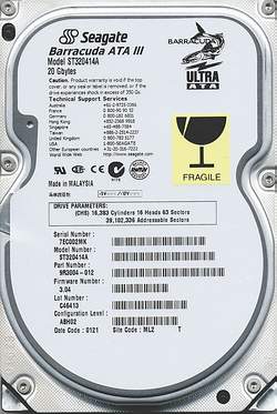
The designations of any hard drive are easy to decipher - they are usually alphanumeric and are built according to similar principles: first - the designation of the manufacturer and model, then the volume in millions of bytes, and at the end - suffixes that clarify the execution, specific characteristics, etc. For example, the "A" suffix indicates an ATA (IDE) interface, and the "S" indicates SCSI. The "V" suffix for many models denotes a cheaper (Value) model, with the exception of Micropolis hard drives, in which the "AV" suffix denotes Audio / Video - an orientation towards uniform data exchange during reading / writing. Examples:
******* Western Digital ******* WD A C 2 635 - 0 0 F 1 2 3 4 5 6 7 8 1 - Western Digital 2 - interface: A - IDE, S - SCSI, C - PCMCIA-IDE 3 - model: C - Caviar, P - Piranha, L - Lite, U - Ultralite 4 - number of physical disks 5 - capacity in million bytes 6 - LED indicator: 0 - none, 1 - red, 2 - green 7 - front panel: 0 - no, 1 - black, 2 - gray 8 - buffer size: S - 8 kb, M - 32 kb, F - 64 kb, H - 128 kb. For refurbished hard drives, after the date of manufacture, the place of restoration is indicated: E - Europe, S - Singapore. ******* Maxtor ******* Mxt 7 850 AV 1 2 3 4 1 - Maxtor 2 - series (7xxx) 3 - capacity in million bytes 4 - suffixes: A - ATA (IDE), S - SCSI, V - Value ****** Seagate ****** ST 5 1080 A PR -0 1 2 3 4 5 6 1 - Seagate Technology 2 - case: 1 - 3.5" 41 mm high 2 - 5.25" high 41mm 3 - 3.5" high 25mm or 5.7" deep 146mm 4 - 5.25" high 82mm 5 - 3.5" high 25mm or 5" deep 127mm 6 - 9" 7 - 1.8" 8 - 8 "9 - 2.5" height 19mm or 12.5mm
Instead of results, I draw your attention to a number of important factors:
- on the extreme sensitivity of hard drives to various kinds of shocks, shocks and shocks;
- that hard drives of the same brand, but from different countries differ sharply in price and quality;
- that you shouldn't buy "Made in China" hard drives;
- that if the warranty is only 6 months, then these hard drives have been lying somewhere for a long time;
Informational capacity hard disk is an important concept for data storage systems. Behind it lies the full volume of the drive. Now two methods of its calculation have become widespread. They give different results, and this is misleading for users who do not understand this issue.
What is the problem?
A person processes information in this way historically, and no one wants to refuse this. We are more comfortable. It consists of numbers from 0 to 9 (some consider from 1 to 10, but this does not change the essence). But the computer processes data in It is based on 0 (no signal) and 1 (voltage). So it turns out that the information capacity of a hard disk can be determined by binary or decimal. In this case, one important point must be taken into account. In the first of them, 1 kilobyte is 2 10 , or 1024 bytes. This value is used by programmers, and this is how all Windows operating systems determine the amount of information today. But in the second case, this value will be equal to 10 3 , or 1000 bytes. This is how people and storage manufacturers think information. As it is easy to understand, a person can buy a hard drive with some characteristics, and the Windows OS will show him a little different information. In this case, the information capacity of the hard disk for the binary system will be less, and for the decimal system - more. But the number remains unchanged. The determining factor in this case is how to count.

Recalculation
Let's make a recalculation on the example of a 500 GB drive (according to the manufacturer) and determine the percentage of losses. To begin with, let's clarify that the prefix "giga" in the decimal system means 10 9, and in binary it means 2 30. First, multiply 500 GB by 10 9 . This will get the size in bytes. To go to the binary system, you need to divide the resulting value 500 x 10 9 by 2 30, and we will get 465 GB. This will be the information capacity of the hard disk in new system. Next, we determine the percentage of losses during the transition between them. To do this, subtract 465 GB from 500 GB and divide the resulting value by 500 GB. The result is 0.07. If this value is multiplied by 100, then we will find out the difference in percent. It will be 7%.
So it turns out that the volume of the drive, which the Windows OS will show, is immediately reduced by the obtained value. Well, if a person understands and understands this. But there are other cases when an offended customer comes to the store and begins to sort things out. At the same time, the seller is accused of selling the “circumcised” drive. The client does not understand that the maximum capacity of a hard disk is actually a constant value. But its value may vary depending on the method of counting. And the difference between them is 7% regardless of volume. This statement is true for all storage devices, including flash drives, floppy disks, and CDs.

Conclusion
The full capacity of a hard disk drive is a key parameter that buyers pay attention to before purchasing. But at the same time, few people think that its value will be less than 7% in the Windows OS. But you need to take this into account and take the device with a certain margin, so that later you don’t buy a second drive.