Over the past few decades, the size and number of networks have grown significantly. There were many types of networks in the 80s. And almost each of them was built on its own type of equipment and software often incompatible with each other. This led to significant difficulties when trying to connect several networks (for example, a different type of addressing made these attempts almost hopeless).
This problem was considered by the International Organization for Standardization ( ISO ) and it was decided to develop a network model that could help developers and manufacturers network equipment and software work together. As a result, in 1984, the OSI model was created - open systems interaction model(Open Systems Interconnected). It consists of seven levels into which the task of organizing network interaction is divided. They are schematically presented in table 16.1.
| Level number | Level name | Unit of information |
|---|---|---|
| Layer 7 | Application layer | data |
| Layer 6 | Executive level | data |
| Layer 5 | Session level | data |
| Layer 4 | transport layer | Segment |
| Layer 3 | network layer | package |
| Layer 2 | Data transfer layer | frame |
| Layer 1 | Physical layer | Bit (bit) |
Although there are various models of networks today, most developers adhere to this generally accepted scheme.
Consider the process of transferring information between two computers. Software generates a layer 7 (application) message consisting of a header and payload. The header contains service information that is necessary for the destination application layer to process the information being sent (for example, it can be information about the file that needs to be transferred, or the operation that needs to be performed). After the message has been generated, the application layer sends it "down" to the presentation layer (layer 6). The received message, consisting of the layer 7 overhead and payload, is presented as a single unit to layer 6 (although layer 6 can read the layer 7 overhead). The presentation layer protocol performs the necessary actions based on the data received from the application layer header and adds its layer header, which contains information for the corresponding (6th) destination layer. The resulting message is passed further "down" to the session layer, where overhead is also added. The padded message is passed on to the next transport layer etc. at each subsequent level (this is schematically shown in Fig. 16.1). In this case, service information can be added not only to the beginning of the message, but also to the end (for example, at the 3rd level, Fig. 16.2). The result is a message containing service information of all seven levels.
Rice. 16.1.
Rice. 16.2.
The process of "wrapping" transmitted data with overhead information is called encapsulation ( encapsulation).
This message is then transmitted through the network in the form of bits. A bit is the smallest piece of information that can be either 0 or 1 . Thus, the entire message is encoded as a set of zeros and ones, for example, 010110101 . In the simplest case, at the physical layer for transmission, a electrical signal, consisting of a series of electrical impulses (0 - no signal, 1 - there is a signal). It is this unit adopted to measure the speed of information transfer. Modern networks usually provide channels with a throughput of tens and hundreds of Kbps and Mbps.
The recipient at the physical layer receives the message in the form of an electrical signal (Fig. 16.3). Next, a process occurs that is the reverse of encapsulation, decapsulation ( decapsulation). At each level, service information is parsed. After decapsulating the message at the first level (reading and processing of the service information of the 1st level), this message containing the service information of the second level and data in the form of payload data and service information of higher levels is transmitted to the next level. At the channel (2nd) level, the system information is analyzed again and the message is transmitted to the next level. And so on until the message reaches the application layer, where it is transmitted as final data to the receiving application.

Rice. 16.3.
An example is a browser call to a web server. The client application - the browser - generates a request to receive a web page. This request is passed by the application to layer 7 and then sequentially to each layer of the OSI model. Having reached the physical layer, our initial request "acquires" the service information of each layer. After that, it is transmitted over the physical network (cables) in the form of electrical impulses to the server. The server parses the corresponding system information of each level, as a result of which the sent request reaches the web server application. There it is processed, after which a response is sent to the client. The process of sending a response is similar to sending a request, except that the message is sent by the server and received by the client.
Because each layer of the OSI model is standardized, consumers can share hardware and software various manufacturers. As a result web server running the Sun Solaris operating system can serve an HTML page to an MS Windows user.
Of course, compatibility can only be ensured up to a certain level. If one machine transmits data in the form of radio waves, and the other in the form of light pulses, then their interaction without the use of additional equipment is impossible. Therefore, the concept of network-independent and network-dependent levels was introduced.
The three lower layers - physical, channel and network - are network-dependent. For example, changing Ethernet to ATM entails a complete change in the protocol of the physical and data link layers.
The top three levels - applications, representative and session - are focused on application tasks and practically do not depend on the physical technology of building a network. Thus, the transition from Token Ring to Ethernet does not require changes in the listed levels.
transport layer is intermediate between the network-dependent and network-independent levels. It hides all the details of the functioning of the lower levels from the upper ones. This allows the application developer not to think about technical means implementation of network message transport.
Together with the name message (message) in ISO standards, the term is used to denote a unit of data protocol data unit(Protocol Data Unit , PDU ). In different protocols, other names are used, fixed by the standards, or simply traditional. For example, in the TCP / IP family of protocols, the TCP protocol divides the data stream into segments, the UDP protocol works with datagrams (or datagrams, from datagram ), the IP protocol itself uses the term packets. Often the same is said about frames or frames.
For a deeper understanding of the principles of the network, we will consider each level separately.
physical layer (layer 1)
As can be seen from the general layout of layers in the OSI model, the physical layer ( physical layer) the very first. This layer describes the communication medium. Standardized physical devices, responsible for the transmission of electrical signals (connectors, cables, etc.) and the rules for the formation of these signals. Let's take a look at all the components of this level in order.
Most of the networks are built on a cable structure (although there are networks based on the transmission of information using, for example, radio waves). Now there are different types of cables. The most common ones are:
- telephone wire;
- coaxial cable ;
- twisted pair;
- optical fiber .
The telephone cable has been used to transmit data since the advent of the first computers. The main advantage of telephone lines was the presence of an already created and developed infrastructure. With its help, you can transfer data between computers located on different continents, as easily as talking to people who are many thousands of kilometers apart. To date, the use of telephone lines also remains popular. Users who are satisfied with a small transmission speed data can access the Internet from their home computers. The main disadvantages of using a telephone cable is the small transmission speed, because the connection does not occur directly, but through telephone exchanges. At the same time, the requirement for the quality of the transmitted signal in data transmission is much higher than in the transmission of "voice". And since most analog PBXs do not cope with this task (the level of "noise" or interference, and the signal quality leaves much to be desired), the data transfer rate is very low. Although when connected to modern digital exchange you can get high reliable speed connections.
Coaxial cable used in networks a few years ago, but today it is a rarity. This type of cable is almost identical in structure to a conventional television cable. coaxial cable– the central copper core is separated by a layer of insulation from the braid. There are some differences in electrical characteristics (a TV cable uses a cable with wave resistance 75 Ohm, in the network - 50 Ohm).
The main disadvantages of this cable is the low transmission speed data (up to 10 Mbps), exposure to external interference. In addition, the connection of computers in such networks occurs in parallel, which means that the maximum possible bandwidth is divided among all users. But, compared to a telephone cable, coaxial allows you to connect closely spaced computers with much better communication quality and higher data transfer rates.
twisted pair (" twisted pair") is the most common means for transferring data between computers. In this type The cable uses a copper wire twisted in pairs, which reduces the amount of interference and interference, both when transmitting a signal through the cable itself, and when exposed to external interference.
There are several categories of this cable. Let's list the main ones. Cat 3 - was standardized in 1991, electrical characteristics allowed to support transmission frequencies up to 16 MHz, was used for data and voice transmission. The higher category, Cat 5, was specifically designed to support high speed protocols. Therefore, its electrical characteristics lie in the range up to 100 MHz. Data transfer protocols of 10, 100, 1000 Mbps work on this type of cable. To date, Cat5 cable has almost supplanted Cat 3. The main advantage of twisted pair cable over telephone and coaxial cables- higher transmission speed data. Also, the use of Cat 5 in most cases allows, without changing the cable structure, to increase performance networks (transition from 10 to 100 and from 100 to 1000 Mbps).
Optical fiber used to connect large network segments that are far apart, or in networks that require a large bandwidth, noise immunity. An optical cable consists of a central conductor of light (core) - a glass fiber surrounded by another layer of glass - a sheath that has a lower refractive index than the core. Spreading through the core, the rays of light do not go beyond its limits, being reflected from the covering layer of the shell. The light beam is usually formed by a semiconductor or diode laser. Depending on the distribution of the refractive index and on the size of the diameter of the core, they are distinguished.
Protocols are a set of rules and procedures that govern how communication takes place. The computers participating in the exchange must work on the same protocols so that as a result of the transfer all information is restored in its original form.
The protocols of the lower layers (physical and channel) related to the equipment have already been mentioned in the previous sections. In particular, these include methods of encoding and decoding, as well as managing the exchange in the network. Some of them will be described in more detail in the chapters of the book devoted to standard networks. And now we should dwell on the features of higher-level protocols implemented in software.
Network adapter communication with network software is carried out by drivers network adapters. It is thanks to the driver that the computer may not know any hardware features of the adapter (its addresses, rules for exchanging with it, its characteristics). The driver unifies, makes the interaction of high-level software with any adapter of this class uniform. The network drivers that come with the network adapters allow you to network programs work equally with boards from different vendors and even with boards from different local networks (Ethernet, Arcnet, Token-Ring, etc.). If we talk about the standard OSI model, then drivers, as a rule, perform functions link layer, although sometimes they also implement part of the functions of the network layer (Fig. 6.1). For example, drivers form a packet to be transmitted in the adapter's buffer memory, read a packet that came over the network from this memory, issue a command to transmit, and inform the computer about packet reception.
Rice. 6.1. Network adapter driver functions in the OSI model
The quality of writing a driver program largely determines the efficiency of the network as a whole. Even with the best performance of a network adapter, a low-quality driver can drastically degrade network traffic.
Before purchasing an adapter card, you should review the Hardware Compatibility List (HCL) published by all network operating system manufacturers. The choice there is quite large (for example, for Microsoft Windows Server list includes over a hundred network adapter drivers). If an adapter of some type is not included in the HCL list, it is better not to buy it.
High level protocols.
There are several standard sets (or, as they are also called, stacks) of protocols that are now widely used:
- a set of ISO/OSI protocols;
- IBM System Network Architecture (SNA);
- Digital DECnet;
- Novell NetWare;
- Apple AppleTalk;
- a set of protocols for the global Internet, TCP/IP.
The inclusion of WAN protocols in this list is quite understandable, because, as already noted, the OSI model is used for any open system: based on both local and wide area networks or a combination of local and wide area networks.
The protocols of the listed sets are divided into three main types:
- Application protocols (performing the functions of the top three layers of the OSI model - application, presentation and session);
- Transport protocols (implementing the functions of the middle layers of the OSI model - transport and session);
- Network protocols (performing the functions of the three lower layers of the OSI model).
Application protocols enable applications to interact and exchange data between them. Most popular:
- FTAM (File Transfer Access and Management) - OSI file access protocol;
- X.400 - CCITT protocol for international traffic email;
- X.500 - CCITT protocol for file and directory services on multiple systems;
- SMTP (Simple Mail Transfer Protocol) is a global Internet protocol for e-mail exchange;
- FTP (File Transfer Protocol) - protocol for the global Internet for file transfer;
- SNMP (Simple Network Management Protocol) - a protocol for monitoring the network, controlling the operation of network components and managing them;
- Telnet is a global Internet protocol for registering on remote servers and processing data on them;
- Microsoft SMBs (Server Message Blocks, server message blocks) and client shells or redirectors from Microsoft;
- NCP (Novell NetWare Core Protocol) and Novell client shells or redirectors.
Transport protocols support communication sessions between computers and guarantee reliable data exchange between them. The most popular of them are the following:
- TCP (Transmission Control Protocol) - part of the TCP / IP protocol suite for guaranteed delivery of data broken into a sequence of fragments;
- SPX is part of the IPX / SPX protocol suite (Internetwork Packet Exchange / Sequential Packet Exchange) for guaranteed delivery of data broken into a sequence of fragments proposed by Novell;
- NetBEUI - (NetBIOS Extended User Interface, extended NetBIOS interface) - establishes communication sessions between computers (NetBIOS) and provides upper layers with transport services (NetBEUI).
Network protocols govern addressing, routing, error checking, and retransmission requests. The following are widespread:
- IP (Internet Protocol) - TCP / IP protocol for non-guaranteed transmission of packets without establishing connections;
- IPX (Internetwork Packet Exchange) - NetWare protocol for non-guaranteed packet transmission and packet routing;
- NWLink is an implementation of the IPX/SPX protocol from Microsoft;
- NetBEUI is a transport protocol that provides transport services for NetBIOS sessions and applications.
All of these protocols can be mapped to one layer or another of the OSI reference model. However, it should be taken into account that protocol developers do not strictly adhere to these levels. For example, some protocols perform functions related to several layers of the OSI model at once, while others only perform part of the functions of one of the layers. This results in protocols different companies are often incompatible with each other. In addition, protocols can be successfully used exclusively as part of their own set of protocols (protocol stack), which performs a more or less complete group of functions. This is precisely what makes the network operating system "proprietary", that is, in fact, incompatible with the standard model of the open OSI system.
As an example, in fig. 6.2, fig. 6.3 and fig. Figure 6.4 schematically shows the relationship between the protocols used by popular proprietary network operating systems and the layers of the standard OSI model. As can be seen from the figures, practically at no level there is a clear correspondence between the real protocol and any level of the ideal model. Building such relationships is rather arbitrary, since it is difficult to clearly distinguish between the functions of all parts of the software. In addition, software companies do not always describe in detail the internal structure of products.
Now let's take a closer look at some of the most common protocols.
The OSI model allows two main methods of interaction between subscribers in the network:
- Interaction method without logical connection (or datagram method).
- A method for interacting with a logical connection.
The datagram method is simplest method, in which each package is considered as an independent object (Fig. 6.5).
The packet with this method is transmitted without establishing a logical channel, that is, without a preliminary exchange of service packets to determine the readiness of the receiver, and also without eliminating the logical channel, that is, without a packet confirming the end of the transmission. Whether the packet will reach the receiver or not is unknown (checking the fact of receipt is transferred to higher levels).
The datagram method imposes increased requirements on the hardware (since the receiver must always be ready to receive a packet). The advantages of the method are that the transmitter and receiver operate independently of each other, in addition, packets can be buffered and then transmitted together, you can also use broadcast transmission, that is, address the packet to all subscribers at the same time. The disadvantages of the method are the possibility of packet loss, as well as the useless loading of the network with packets in the absence or unavailability of the receiver.
The logical connection method (Figure 6.6, Figure 4.5) was developed later than the datagram method and has a more complicated order of interaction.
With this method, the packet is transmitted only after a logical connection (channel) is established between the receiver and the transmitter. Each information packet is accompanied by one or more service packets (connection establishment, receipt confirmation, retransmission request, connection termination). A logical channel may be set up for the duration of one or more packets.

Rice. 6.2. The relationship between the levels of the OSI model and Internet protocols
Rice. 6.3. Relationship between the levels of the OSI model and operating system protocols Windows Server

Rice. 6.4. Relationship between the layers of the OSI model and the protocols of the NetWare operating system

Rice. 6.5. Datagram method

Rice. 6.6. Method with logical connection
The logical connection method, as already mentioned, is more complicated than the datagram method, but much more reliable, because by the time the logical channel is closed, the transmitter is sure that all its packets have reached their destination, and they have arrived successfully. There is no network congestion due to useless packets with this method. The disadvantage of the logical connection method is that it is quite difficult to resolve the situation when the receiving subscriber is not ready for exchange for one reason or another, for example, due to a cable break, power failure, network equipment failure, computer failure. In this case, an exchange algorithm is required with the repetition of an unacknowledged packet a given number of times, and the type of the unacknowledged packet is also important. This method cannot transmit broadcast packets (that is, addressed to all subscribers), since it is impossible to organize logical channels with all subscribers at once.
Examples of protocols that use the datagram method are the IP and IPX protocols.
Examples of protocols that work with the logical connection method are TCP and SPX.
Precisely in order to combine the advantages of both methods, these protocols are used in the form of related sets: TCP / IP and IPX / SPX, in which a higher-level protocol (TCP, SPX) operates on the basis of a lower-level protocol (IP, IPX) , ensures that packets are delivered correctly in the required order.
The IPX/SPX protocols developed by Novell form a set (stack) used in network software tools fairly widespread Novell (NetWare) local area networks. It is a relatively small and fast protocol that supports routing. Application programs can access the IPX layer directly, for example, to send broadcast messages, but are much more likely to work with the SPX layer, which guarantees fast and reliable packet delivery. If speed is not too important, then application programs use an even higher level, such as the NetBIOS protocol, which provides a convenient service. Microsoft has proposed its own implementation of the IPX/SPX protocol, called NWLink. The IPX/SPX and NWLink protocols are supported by NetWare and Windows operating systems. The choice of these protocols ensures network compatibility of any subscribers with these operating systems.
The TCP/IP protocol suite (stack) was specifically designed for wide area networks and for internetworking. It is initially focused on the low quality of communication channels, on the high probability of errors and disconnections. This protocol is adopted in the worldwide computer network Internet, a significant part of the subscribers of which are connected via dial-up lines (that is, ordinary telephone lines). Like the IPX/SPX protocol, the TCP/IP protocol also supports routing. It is based on high-level protocols such as SMTP, FTP, SNMP. The disadvantage of the TCP / IP protocol is a lower speed than IPX / SPX. However, TCP/IP is now also used in local networks to facilitate negotiation of LAN and WAN protocols. Currently, it is considered the main one in the most common operating systems.
The TCP / IP protocol stack often includes protocols of all upper layers (Fig. 6.7). And then we can already talk about the functional completeness of the TCP / IP stack.
Both IPX and IP are the lowest-level protocols, so they directly encapsulate their information, called a datagram, in the data field of a network packet (see Figure 4.6). In this case, the datagram header includes addresses of subscribers (sender and recipient) of a higher level than MAC addresses - these are IPX addresses for the IPX protocol or IP addresses for the IP protocol. These addresses include network and host numbers, host (individual subscriber ID). At the same time, IPX addresses (Fig. 6.8) are simpler, have only one format, and an IP address (Fig. 6.9) can include three formats (classes A, B and C), differing in the values of the three initial bits.
Rice. 6.7. Relationship between the layers of the OSI model and the TCP / IP protocol stack
Rice. 6.8. IPX address format

Rice. 6.9. IP address formats
Interestingly, the IP address has nothing to do with the MAC addresses of subscribers. The node number in it is assigned to the subscriber regardless of his MAC address. As a station identifier, the IPX address includes the full MAC address of the subscriber.
The network number is a code assigned to each specific network, that is, to each broadcast area of the general, single network. The broadcast area is understood as a part of the network that is transparent to broadcast packets and passes them freely.
The NetBIOS (Network Basic Input/Output System) protocol was developed by IBM for the IBM PC Network and IBM Token-Ring, modeled after the BIOS personal computer. Since then, this protocol has become a de facto standard (it is not officially standardized), and many network operating systems include a NetBIOS emulator for interoperability. Initially, NetBIOS implemented the session, transport, and network layers, but later networks use standard protocols at lower levels (for example, IPX / SPX), leaving only the session layer for the NetBIOS emulator. NetBIOS provides a higher level of service than IPX/SPX, but is slower.
Based on the NetBIOS protocol, the NetBEUI protocol was developed, which is an extension of the NetBIOS protocol to the transport layer. However, the disadvantage of NetBEUI is that it does not support interworking and does not provide routing. Therefore, this protocol is used only in simple networks not designed to connect to the Internet. Complex networks rely on the more versatile TCP/IP and IPX/SPX protocols. The NetBEUI protocol is now considered obsolete, although even in operating system Windows XP provides for its support, however, only as an additional option.
Finally, the OSI protocol suite already mentioned is a complete set (stack) of protocols, where each protocol exactly corresponds to a certain level of the standard OSI model. The suite contains routed and transport protocols, the IEEE 802 series of protocols, a session layer protocol, a presentation layer protocol, and several application layer protocols. So far, this set of protocols has not received wide distribution, although it is fully consistent with the OSI reference model.
Protocols implemented at the Network layer that carry user data include:
- Internet Protocol version 4 (IPv4)
- Internet Protocol version 6 ( IPv6)
- Novell packet interworking ( IPX)
- AppleTalk
- Network Service without Connection Establishment ( CLNS/DECnet)
The Internet Protocol (IPv4 and IPv6) is the most widely used Layer 3 data transfer protocol, which will be the focus of the following. Discussion of other protocols will only be superficial.
IP Protocol - An Example of a Network Layer Protocol
Role of IPv4
As shown in the figure, the Network Layer services implemented in the TCP/IP protocol stack include Internet Protocol (IP). Version 4 of IP (IPv4) is currently the most widely used version of IP. This is the only Layer 3 protocol that is used to transmit user data over the Internet and will be taken as an example. network layer protocols in this and subsequent articles.
Version 6 of IP (IPv6) is being developed and implemented in some areas. IPv6 will work alongside IPv4 and may replace it in the future. The services provided by IP, as well as the packet header structure and content, are defined by either IPv4 or IPv6. These services and packet structure are used to encapsulate UDP datagrams or TCP segments for their passage through the internetwork.
The characteristics of each protocol are different. Understanding these characteristics will allow you to understand the operation of the services described by the respective protocol.
The Internet Protocol was designed as a low overhead protocol. This provides only the functionality needed to deliver a packet from source to destination over a system of interconnected networks. The protocol was not designed to monitor and control the flow of packets. These functions are performed by other protocols at other layers.
Main characteristics of IPv4:
- Connectionless - No sessions are established before packets are sent.
- Non-guaranteed delivery (unreliable) - No additional overhead is used to guarantee the delivery of packets.
- Environment independent - Operates independently of the medium carrying the data.
Network layer protocols were developed long before the OSI architecture was proposed and standards for network services were adopted.
To clarify the place of the various protocols of this layer in the OSI reference model, the network layer architecture (ISO 8648) was developed. This document distinguishes 3 sublayers at the network layer. It is assumed that the services of a real subsystem can be:
In the last two cases, to provide a standard service, it is necessary to implement a certain set of additional functions.
The figure shows the protocols of the three network sublayers.
Network Layer Protocols in Packet-Switched Networks
AT computer networks packet-switched (PS) protocols are distinguished at the network level by three functional types:
Packet processing protocols - define packet formats and procedures for their processing in subscriber and communication systems
Packet control protocols - contain decision-making algorithms on the choice of packet transmission routes, limiting the input load, packet control, set the composition of service information that systems exchange, and the rules for responding to it.
Service information transfer protocols define the formats of service information and procedures for its transmission.
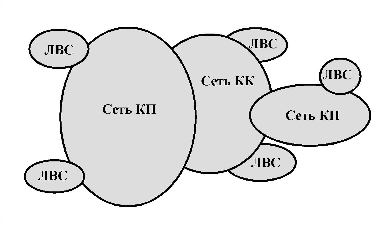
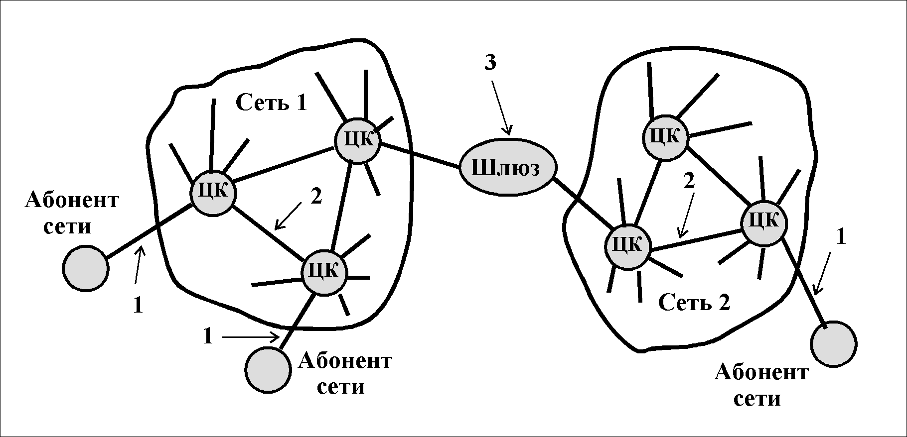
In addition to this classification, depending on the type of interacting systems, the following three network protocols are distinguished (see Fig.):
E 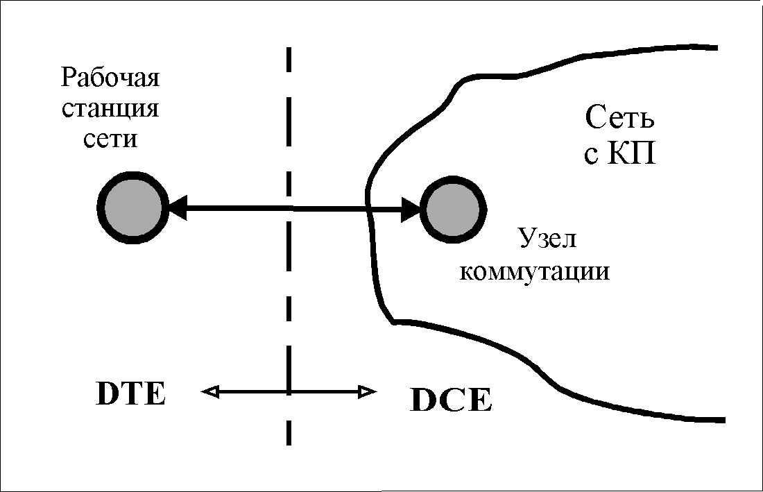 This is one of the first documents developed to regulate the development of the three lower layers (including network) for packet-switched networks.
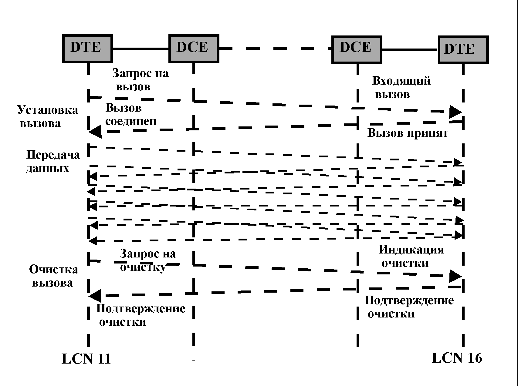
X.25 contains no routing algorithms. The Recommendation is a formal specification for the interfacing of DTEs and DCEs (see figure). Under DTE refers to any data terminal equipment (DTE), and DCE is the Data Link Termination Equipment (DCE). The standard is asymmetric, because only one side of the connection between subscribers through the network is defined.
H 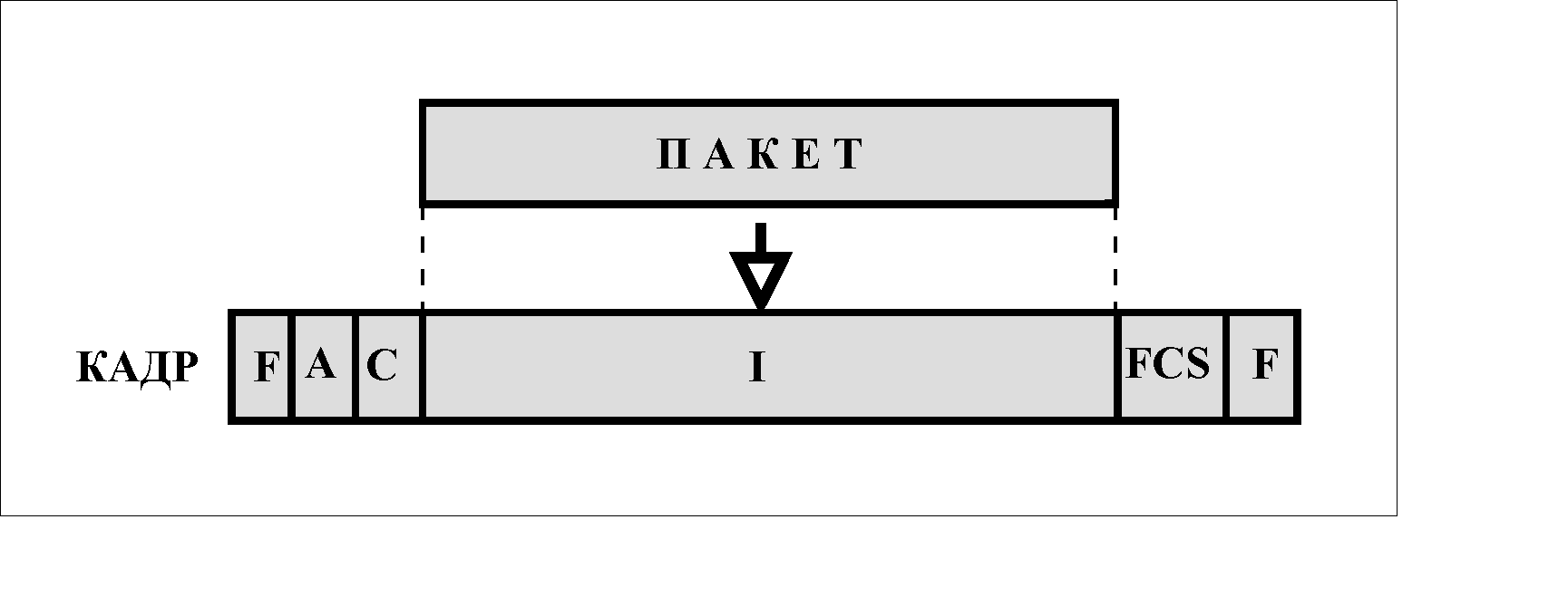 and the second layer uses the LAPB subset of the HDLC protocol.
The layer 3 (network) packet (see figure) is transported in the information field (I) of an HDLC protocol frame operating in LAPB mode.
Packet layer features (X.25/3 protocol)
The protocol uses the principle of virtual circuits (in X.25 they are called logical channels). Logical channels are obtained by multiplexing packets of different users in one physical channel. Up to 4095 logical channels can be assigned on such a physical channel. The logical channel numbers are used to identify the DTE that is connected to the network.
flow control
Two mechanisms are used: the transmission window and the suspension of the transmission. Data packets are numbered modulo 8 (an extended format is allowed - modulo 128), i.e. 0 1 2 3 4 5 6 7 0 1 2 3 4 5 6 7 0 1 2 3 4 5 etc. The packet receiver keeps track of the sequence numbers P(S) of the received packets and indicates in the P(R) field of the response packets the sequence number of the packet that it expects (it is assumed that all numbers before that have already been received correctly by it).
Transfer window
D 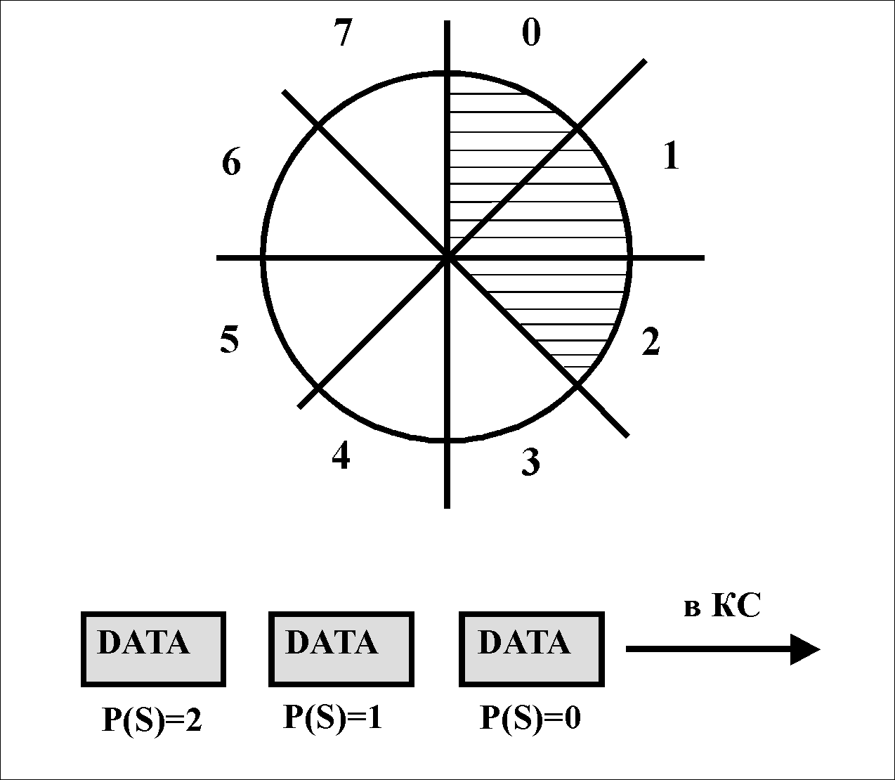 to regulate the flow of data is used window mechanism. The W window is the number of packets that the DTE can send without being acknowledged. The X.25/3 protocol recommends W = 2, but it is up to any network administration to set specific values.
The figure shows the initial state of the DTE with W=3. Such a station can transmit a maximum of 3 packets without acknowledgment, i.e. packets with P(S)=0, P(S)=1 and P(S)=2. The DCE keeps track of the number sequence and may inform the DTE of the next P(R) packet number expected to be received. Thus, it acknowledges the receipt of all packets with sequence numbers up to (P(R)-1) inclusive. This control only applies to DTE/DCE pairing.
P 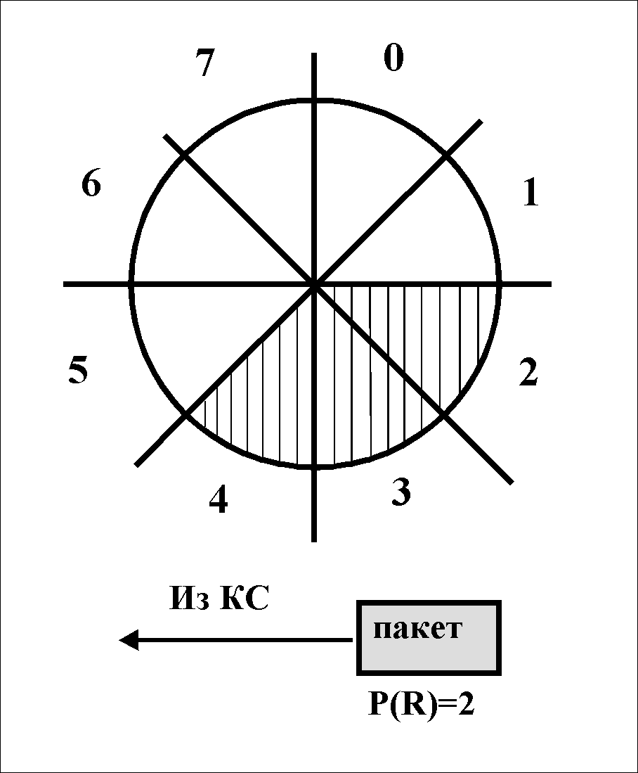 Let us assume that the number P(R)=2 is reported in the response packet from the DCE. This means that two packets are acknowledged. The window moves (see fig.). The DTE may now continue transmitting up to P(S)=4.
Since data flows in both directions of the interface, the same flow control from the DCE is performed by the DTE.
Local (at the DTE/DCE interface level) flow control has been discussed above. In addition to the local one, the window mechanism can also be used to control the flow over a virtual channel. If a special service bit (D-bit) in a packet is set to "1", this means that end-to-end (end-to-end, ie DTE - DTE) delivery of the packet is required.
Suspend packages
If it is necessary to urgently suspend the issuance of packets by a partner, an additional flow control mechanism is applied. Suppose the DCE wants to suspend the flow of data packets from the DTE. Then it issues a packet "Not ready for reception" (RNR) - Receive not Ready (see Fig.).
The P(R) number in the packet acknowledges all packets up to (P(R)-1) inclusive.
To resume reception, a Receive Ready (RR) packet is issued. Such a packet also contains a P(R) number.
P  Protocol X.25/3 procedures
Data transfer The size of the data field can be from 16 to 4096 bytes.
Reset Procedure Used in case of errors in a particular virtual channel. Triggered by a Reset Request or Reset Indication packet from the DTE or DCE. The virtual circuit is not disconnected. It is being initialized. The packet counters on both ends are set to "0". All packets in transit are discarded.
Restart procedure Applies in case of serious errors affecting the entire DTE/DCE interface. All virtual circuits between DTE and DCE are disconnected. Next, you need to install all the channels again. The packages used are Restart Request and Restart Indication.
P 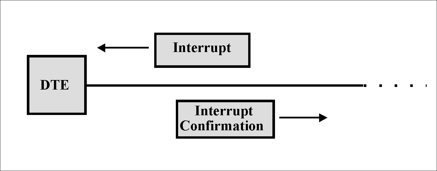 transmission of urgent data
It is possible to transfer data without following flow control procedures.
transmission of urgent data
It is possible to transfer data without following flow control procedures.
For this, the Interrupt package is used. The maximum length of data in a packet is 32 bytes. This packet bypasses all queues along the way and is received at the other end, even if the DTE does not receive normal data. Each packet (see figure) sends an Interrupt Confirmation. The transmitting DTE does not send the next Interrupt packet until it receives an acknowledgment for the previous one.
Optional Services There are enough of them. Among them, for example:
Retransmission of packets(using a special “Reject” packet. The DTE may request that packets from the specified P(R) number and all following it be transferred to it).
Call forwarding. If the called DTE is faulty or busy, then the call is forwarded by the network to another DTE.
Formation of a closed user group. These users can only interact with each other. You can, for example, allow the DTE to make outgoing calls without restriction, but only accept incoming calls from a closed group of users.
Reverse billing(a request to the network to charge all billing costs to the called subscriber), etc.
THEME: Network layer of data transfer. Network layer protocols.
network layer (networklayer) - level of interconnection(internetworking) – (the third level of the OSI model), serves to form a single transport subsystem that combines several networks. At the same time, networks can use completely different principles for transmitting messages between end nodes and have an arbitrary communication structure.
The data that comes to network layer and which need to be transmitted over the composite network are provided with a network layer header.
The data together with the header form a packet. The network layer packet header carries information about the number of the network to which the packet is intended, as well as other service information necessary for the successful transition of the packet from a network of one type to a network of another type. Such information may include, for example:
Packet fragment number required for successful assembly operations - disassembly of fragments when connecting networks with different maximum packet sizes;
Packet lifetime, indicating how long it travels over the internet, this time can be used to kill "lost" packets;
Quality of Service is a route selection criterion for inter-network transmissions - for example, a node - a sender may require a packet to be transmitted with maximum reliability, possibly at the expense of delivery time.
The main network layer protocols are network protocols (for example, IP or IPX) and routing protocols ( RIP, OSPF, BGP and etc.).
An auxiliary role is played by such protocols as - the protocol of inter-network control messages ICMP ( Internet Control Message Protocol ) , which is designed to exchange information about errors between network routers and the source node of the packet. With the help of special messages, ICMP reports about the impossibility of delivering a packet or about a packet timeout, about a change in the forwarding route, about the state of the system, etc. Group control protocol IGMP and address resolution protocol ARP.
Network protocols and routing protocols are implemented as software modules on end nodes - computers, often called hosts and on intermediate nodes - routers, called gateways.
Network protocols are designed to transfer user data, while routing protocols collect and transmit over the network only service information about possible routes. Network protocols actively use the routing table in their work, but they do not build it or maintain its contents. These functions are performed by routing protocols. Routing protocols can be built on the basis of different algorithms that differ in the way they build routing tables, how to choose the best route, and other features of their work. There are single-hop and multi-hop routing algorithms.
At the network level, a correspondence is also established between the IP address and the hardware address (MAC address). The establishment is carried out by the address resolution protocol - ARP, which for this purpose looks through the ARP - tables. If the desired address is missing, then a broadcast ARP request is performed.
Network layer functions.
The functions of the network layer include the following tasks:
1. Packet transmission between end nodes in composite networks. The network layer acts as a coordinator that organizes the work of all subnets that lie in the path of the packet's progress through the composite network. A composite network (Internet) is a collection of several networks, also called subnets, that are interconnected by routers.
2. The choice of the packet transmission route, the best according to some criterion.
3. Negotiation of different link layer protocols used in separate subnets of the composite network. To move data within subnets, the network layer refers to the technologies used on those subnets.
4. At the network level, one of the most important functions of the router is performed - traffic filtering. Routers allow administrators to set different filtering rules. For example, to prohibit the passage of all packets to the corporate network, except for packets coming from the subnets of the same enterprise. Filtering in this case occurs by network addresses. The router software can implement various packet queuing disciplines, as well as various priority service options.
5. At the network level, the checksum is checked, and if the packet arrived damaged, then it is discarded (the network level does not deal with error correction). The packet lifetime is also checked - whether it exceeds the allowable value (if it exceeded, then the packet is discarded).
Routing principles.
The network layer provides the ability to move packets through the network using the route that is currently more rational.
A route is a sequence of routers that a packet must traverse from the sender to the destination. In complex multilayer networks, there are almost always multiple alternative routes for packets to travel between two end nodes. The task of choosing a route is solved by both end nodes - computers and intermediate nodes - routers based on routing tables. Routers usually automatically create routing tables by exchanging overhead information; for end nodes, routing tables are often created manually by administrators and stored as permanent files on disks. Routers have multiple ports for connecting networks, each router port has its own network address and its own local address. If the router has a control unit, then this unit has its own address, at which it is accessed by a central control station located somewhere in the composite network.
Routers use routing protocols to map links in varying degrees of detail. Based on this information, for each network number, a decision is made about which next router should forward packets destined for this network in order for the route to be rational. The results of these decisions are entered in the routing table.
Routing protocols include protocols such as RIP, OSPF, BGP; ICMP Internet Control Message Protocol.
Large networks are divided into autonomous systems, autonomous systems are networks attached to the backbone, having their own administration and their own routing protocols.
Routing protocols are divided into external and internal. External protocols (EGP, BGP) carry routing information between autonomous systems, while internal protocols (RIP, OSPF) are used within a particular autonomous system.
The BGP protocol allows you to recognize the presence of loops between autonomous systems and exclude them from intersystem routes.
The RIP protocol (Routing Internet Protocol) is one of the earliest protocols for the exchange of routing information and is still extremely common due to the simplicity of routing. The RIP protocol has several versions, for example, for the IP protocol, there is a version of RIPv1 that does not support masks and a version of RIPv2, this is a protocol that conveys information about network masks. Using the RIP protocol, a routing table is built. The first column of the table lists the numbers of networks included in the Internet. On each line, the network number is followed by the network address of the port of the next router to which the packet should be sent in order for it to move towards the network with this number along a rational route. The third column indicates the output port number of this router. The fourth column indicates the distance to the destination network.
Table 1. Routing table
As a distance to the destination network, the RIP protocol standards allow various kinds of metrics: hops, metrics that take into account throughput, latency, and network reliability. The simplest metric is the number of hops, that is, the number of intermediate routers that a packet needs to traverse to reach its destination network. The RIP protocol works successfully in relatively small networks with up to 15 routers.
OSPF (Open Shortest Path Fist) protocol was developed to efficiently route IP packets in large networks with complex topology, including loops. It is based on a link state algorithm that is highly resistant to network topology changes. When choosing an OSPF route, routers use a metric that takes into account the throughput of the constituent networks. The OSPF protocol takes into account the quality of service bits, a separate routing table is built for each type of quality. The OSPF protocol has a high computational complexity, so it most often runs on powerful hardware routers.