Lecture 6:
Use case diagrams: close-up
A few words about the requirements
So let's talk about the requirements. We generally understand what this is - when a customer describes to us what exactly he wants, we always hear phrases like “I would like the update check to be carried out automatically, like in antiviruses”, “I want a big green button in the center of the window , which starts the process", " program should allow you to view and print reports”, “and everything should be beautiful, with translucency, like in Vista”, “a confirmation should be displayed when exiting”, etc., etc. Of course, as real developers, we understand that that the customer never knows what exactly he needs, and if he understands, he cannot explain. But phrases are always By essentially the same! They describe how the customer imagines the system, what the customer wants from the system, the functionality that he expects from it, the requirements that he places on it.
Each large use case defines a distinct goal that the actor achieves, such as purchasing a product or, from a supplier's perspective, providing products for sale. Once you have clearly stated these goals, you can go into more detail about the achievements of each goal and variations of the main goals.
Avoid decomposition if used in many parts. Use cases are about the experience of your users of the system, not about its internal workings. Additionally, you will usually find it more productive to create early working versions of the code, rather than spending time developing use cases in many details.
If we turn to the classics, for example, to the same “gang of three” (Jacobson, Butch, Rambo), we learn that a requirement is a desired functionality, property or behavior of a system. The development process begins with the collection of requirements. BY. If we depict the development process BY as " black box"(we are sure the reader knows what this is, if not - Wikipedia is at your service), the output of which we get software, then on entrance This “black box” will provide exactly the set of requirements for the software product ( rice. 6.1)!
You can summarize the relationships between basic and more detailed use cases in a use case diagram. In the illustration, the meal order includes payment, select Menu and select a menu item. Each of the more detailed use cases includes a step that the actor or actors must perform to achieve the overall goal of the use, including.
The arrow should point to the most detailed use case. You can share included use cases. In this example, ordering food and subscribing to reviews, use two cases for payment. The goals and scenarios of an included use case make sense regardless of the fact that they can be included in use cases that are created later.
Rice. 6.1.
By the way, what diagram does this picture resemble? Right, activity diagram. And the choice of this particular diagram is absolutely justified here - remember, we said that activity diagrams often used to describe business processes? The only caveat: usually the development process does not end with the release of a software product - a new one is coming iteration, new, updated requirements, a new version etc.
Sets the order of detailed steps
- Structure usage descriptions in different detail layers.
- Avoid repeating common scenarios across different use cases.
To make the query clean, you can use an artifact to attach a separate document to the use case being used. The following example adds an activity diagram to the food order. Alternatively, you can use a text document that has a list of steps or a screen capture sequence.
By the way, let's return to the requirements. Yes, we said that the input of our “black box” is a set of requirements. But in what form? How are they documented, these requirements? I think most readers remember what it is technical task- the main document, without which no project was started in Soviet times. The document was large, multi-page, with a clear structure determined by GOSTs (state industry standards). And he described By in essence, nothing more than the requirements for the system being created!
Pay attention to these naming conventions when using an activity diagram. The name of all activities is the same as the use case. . Use a generalization relationship to show that a specialized use case is a specific way of achieving the goals expressed by another general use case. The open arrow should point to the most common use case.
For example, payment summarizes payment by credit card and payment by cash. Specialized use cases are considered to inherit the purposes and participants of the general use. The general use case does not require custom scripts; their specializations are described various ways achieving goals.
Technical task - thing By- good in its own way. But time passed, standards, notations, and ways of describing requirements changed. And so gradually technical task conceded place a set of artifacts consisting of two types of documents:
· use case diagrams ;
· non-functional requirements.
Create a generalization link with a large arrow pointing to a new case general purpose.
- Create and use a generic version of the new name.
- Click Generalize in the toolbar.
- Click on the general use case.
Actors shared among specialized use cases can be transferred to the general use case. Use an extension link to show that one use case can add functionality to another use case under certain circumstances.
Use case diagrams make up use case model(use cases, use-cases). Precedent- this is the functionality of the system, allowing the user to obtain some meaningful, tangible and measurable result. Every precedent corresponds to a particular service provided by the modeled system in response to request user, i.e. determines how to use this system. Exactly By For this reason, use cases, or precedents, often appear in Russian terminology as use cases. Use cases are most often used to specify external requirements for a system being designed or to specify the functional behavior of an already existing system. In addition, use cases implicitly describe typical ways for a user to interact with the system, allowing them to work correctly with the services provided by the system.
Separate the use case into main parts and expand
For example, an example use case for a regular site login might involve registering a new user - but only when the user does not have account. An extension use case represents the script steps that will be part of the main use case scenarios. The script and extension target will always be read in the context of the main use case, so they should not be used independently.
Separating extensions can be useful to describe such situations. There are additional participants who participate only if the extension is used. You can show each version as a separate subsystem in a usage diagram.
- For example, an administrator must approve a customer's entry on a website.
- A separate subsystem will handle the extension use case.
- This extension is only available for certain versions of the system.
Non-functional requirements - this is a description of such properties of the system as features of the environment and implementation, performance,extensibility, reliability etc. Often non-functional requirements are not tied to a specific use case and therefore are placed in a separate list additional system requirements ( rice. 6.2).
Drag existing use cases inside or outside the subsystem to match your content.
- On the toolbar, click Subsystem, and then click Diagram.
- The diagram shows the subsystem.
- Drag the corners of the subsystem to fit.
Use cases outside the scope
It's usually helpful to include use cases in your diagrams that are part of the company but are not handled by the system you're developing. For example, providing food may be shown as a use case involving restaurant participants and customer service, but outside the responsibility of the website application. You can create multiple subsystem boundaries to show how different cases are handled by different system components. For example, adding a restaurant rating can be handled on a separate Forum website.
Rice. 6.2.
But let's return to precedents (use cases). It is the responsibility of the systems analyst to identify precedents and actors. And he does this in order to:
· clearly distinguish between the system and its environment;
You can use different subsystem thresholds for illustration different versions systems. For example, a payment usage example may be included in a version 2 site, but not in version 1. This means that the system helps customers place their orders. However, they must pay the restaurant directly.
Use dependency relationships to bind subsystems that represent different versions or variants. Creating a use case, depending on your point of view, is not much different from programming. From the same point of view, one can do a good job in both modeling and coding.
· determine which actors interact with the system and how exactly, what functionality (use cases) is expected from the system;
· define and describe in a domain dictionary (glossary) general concepts, which are necessary for a detailed description of the system functionality (precedents).
This type of activity is usually performed in the following sequence:
Did you know that you can use an object-oriented programming language and make software with non-object-oriented programming? Note: unfortunately, in the area software Many professionals attach great importance to quality and do not get caught up in details. They do things on their own without knowing in detail what they are doing or why they are doing it.
It's not always the professional's fault, it's an area with a lot of unprepared leaders. But it depends on the quality of what was produced. There will always be an arrogant professional who will analyze the usage diagram and say: Did you waste your time on this? A drawing with figures, little balls and little things that tie things together?
1. Identification of actors.
2. Definition of precedents.
3. Drawing up a description of each precedent.
4. Description of the use case model as a whole (this stage includes the creation of a domain dictionary).
Initially, the requirements are formalized in the form of a regular text document, which is created either by the user himself, or by the user and the developer together. Next, the requirements are presented in table form. Precedents are placed in the left column, and actors participating in the precedent are placed in the right column.
Someone else might say: So, you point. Apart from the irony and lack of softness, really, to make a "drawing" with stick and ball puppets, putting these things together without having any low quality items in the material made, really has no usefulness.
This wastes time, time that could be used on things more useful to the project. But if it's a job well done, if it's a quality diagram and actually explores the capabilities of the use case modeling technique, it uses the technique correctly and helps the whole team understand and implement the scope of the project better, it generates value, it becomes relevant there.
Let's look at an example. The secretary places it on the server menu lunch dishes for the week. Employees should be able to familiarize themselves with menu and place an order by selecting dishes for each day of the next week. Office-the manager must be able to generate an invoice and pay it. The system must be written in A.S.P..NET. This is a simple Internet application to automate lunch orders in office.
Relationship between use cases
The relationships between use cases, especially for professionals who have first contact with the subject, almost always create some confusion. Let's get into what each of the three relationship types means. The relationship direction is the use case that is enabled for the enabled use case. The direction of the relationship is from the extensor use case to the extended use case. Many experts say that this should not be understood as inheritance of object orientation, but in my opinion it should be Yes, we are just at another level of abstraction, but the end product of this modeling will be coded software.
We think everything is clear here. Table with a description of the requirements could be, for example, this:
| Precedent | Actor |
| post menu | secretary The direction of the relationship is always from the generator to the generalized. Below is a diagram with a scenario similar to the one described above, illustrating the relationship. In the diagram we have four use cases and three different relationships: include, extend and generalize. The Material Request use case includes the Inventory Check use case. This is because whenever there is a request for material, there will always be a summary request to see if the material is available. If ever there is, the correct relationships will be included. |
| view the menu | |
| make an order | employee, secretary, office manager |
| create an account | Office Manager |
| pay the bill The Material Purchase use case extends the use of the Material Request use case. This is because when a material is requested, if the material is out of stock, you may be asked to purchase the item. But you cannot be asked to purchase because the item may be in stock. If a purchase can be requested, the correct relationship is an extension. The Purchase Material use case summarizes the Purchase Order use case. Thus, it is not justified to duplicate the corresponding specification in another use case, it is enough to repeat what is already ready, but generalized to such an extent that it can be used by someone who specializes in it. | Office Manager |
Nowhere does it say that the system must be written in A.S.P..NET. It’s clear why: this is a non-functional requirement! And also, it is obvious that the secretary and office-manager are also employees. The reader who has carefully read the previous lectures will suspect that in this case, when creating a model of precedents, speaking about the actors, generalization could be applied. Really, use case diagram, built on the basis of this table, can be, for example, like this ( rice. 6.3):
The importance of proper use in relationships
Specifications are interpreted and, based on the interpretation, allow the creation of executable programs. The higher the quality in the specification, the easier it will be to understand, and the more correct the interpretation will be for someone using it. This tool generates speed in the production of other models, reduces the number of potential defects and generates other various benefits.
The clarity and correctness of the relationships between use cases directly affects the quality of the project. Use Example Scripts.
- Plinio Ventura Thank you for participating, Marcelo, whatever you feel.
- Plinio Ventura Thank you, Ronald!
Rice. 6.3.
Use case diagrams and their notation
Well, we have an example chart. So, what elements do we see on it? The first thing that catches your eye is the big rectangle, inside which ellipses are placed, indicating, as we already understood, precedents. The name of the modeled system is indicated in the upper part of the rectangle, and it is called within the system (system boundary, subject boundary),context or simply system. This diagram element shows the boundary between what you like analyst shown in the form of precedents (within this framework), and by what you depicted as actors (outside them). Most often this rectangle is shown boundaries of the simulated system itself. That is, inside the boundary there are precedents - the functionality that the system implements (and in this sense, precedents can be considered as representations of subsystems and classes of the model), and outside - characters: users and others external entities, interacting with the modeled system.
It should be said that the framework of the system is depicted quite rarely in use case diagrams, since they are implicitly implied by the diagram itself. By Essentially, this element does not add any additional meaningful information to the diagram, so its use is a matter of taste for the analyst. The appearance of the system framework on the use case diagram is most often dictated by the characteristics of the personal design style.
In addition to the framework of the system or its context in the diagram, we see two more types of entities associated with it - these are characters(actors) and precedents. Let's start with the ectors. Quite often in Russian-language literature By UML To designate the characters you can find the term " actor". In principle, its meaning is more or less clear to the original English term he is in tune. Moreover, there is another reason for this translation. Which word the first thing that comes to your mind when you hear word "actor"? Yes, of course - word"role"! It is about roles that we will soon talk about when we try to figure out what is hidden behind the concept of “actor”. In the meantime, may the reader forgive us, we will continue to use the word “actor” - a transcription of the original term. I remember we once wrote about our attitude to the literal translation of terminology...
So, what is the meaning of the concept of actor? Ector is a set of roles played by user during interaction with some entity (system, subsystem, class). An actor can be a person, another system, a subsystem, or a class that represents something beyond the entity in question. Actors “communicate” with the system by exchanging messages. By clearly identifying the actors, you thereby clearly define the boundary between what is inside the system and what is outside - the framework of the system.
Perhaps the words “roles performed by the user” in the definition of an actor do not sound very clear. This concept is explained very funny in Zicom Mentor:
a role is not a specific user, but a kind of hat that a person puts on when interacting with an entity.
Indeed, put on a pirate hat and you are Captain Jack Sparrow, but put on a top hat and you are Jack the Ripper! Just kidding... "Physical" user can play the role of one or even several actors, performing their functions during interaction with the system. Conversely, the role of the same actor can be performed by several users.
On the charts UML ectors are depicted as stylized men, because, as you, of course, remember, the idea was to create a notation, any symbol of which can easily be depicted by hand ( rice. 6.4):
Rice. 6.4.
Despite the “human” appearance of this designation, we should not forget that actors are not necessarily people. An actor, as we said earlier, can be an external system, a subsystem, Class etc. By the way, little man ("stick-person" ) is not the only ector designation used in UML. In case diagrams, it is usually the “humanoid” form of the actor that is used, but in other diagrams, and especially in cases where the actor has attributes, which is important to show, the image of the ector as a class with a stereotype is used<
Rice. 6.5.
Actors, as we have already said, communicate with the system through messages, but if we speak at a higher level of abstraction, in terms of the precedent model, then they interact with the system through precedents. One and the same actor can be associated with several precedents, and vice versa, one precedent may be associated with several different actors. Associations between an actor and a precedent are always binary - that is, they represent a one-to-one relationship; the use of multiplicity is unacceptable. This does not contradict what was said above: indeed, one actor can be associated with several precedents, but only through separate associations - By one for each precedent. We saw this in our example. By the way, there we saw associations depicted not just as lines, but as arrows. We think the meaning of this designation is quite clear: this directed association and the arrow (as in other diagrams) is always directed towards the entity from which something is required, whose service is used, etc.
And one more thing - actors cannot be connected to each other. The only acceptable attitude between actors - generalization(inheritance). Again, in our example of ordering lunch at office, you could see exactly this type of relationship between actors. This doesn't mean that in real life office-the manager and the secretary (and indeed any two employees) cannot communicate: it’s just that when creating a precedent model, such communication does not fall into our area of interest and is considered insignificant.
Another type of element found in use case diagrams, moreover, which gives them their name, is the actual precedents, or use cases. Precedent is a description of a set of sequential events (including possible options) performed by the system that lead to the result observed by the actor. Use cases describe the services a system provides to the actors with which it interacts. Moreover precedent never explains “how” the service works, but only describes “what” is done.
Precedents are depicted in the form of an ellipse, inside the outline of which the name (description) of the precedent is placed. The use case name is usually much longer than the names of other model elements. Why this is so is, in principle, clear: the name of the use case describes the interaction of the actor with the system, talks about what messages they exchange with each other. In our example with ordering lunch, we saw several precedents, and the reader probably noticed that the name of the precedent is, rather, the name of the script that is reproduced during the interaction of the actor with the system. And this is always a description from the actor's point of view, a description of the services provided by the system to the user. Let us give an example of a simple diagram illustrating what we have said about precedent notation ( rice. 6.6).
Rice. 6.6.
In this example, a passenger can buy a ticket for some type of transport at the service desk. Buying a ticket is the name of the scenario, By which the actor (passenger) can interact with the system (cash register). Notice this not a description script, namely the title - it tells us What makes an ector during interaction, but does not say how exactly! And yet - precedents determine disjoint behavior scenarios. The execution of one use case cannot be interrupted by the operation of another use case. In other words, the execution of one use case cannot be interrupted by events or actions caused by the execution of another use case. Precedents act as atomic transactions, the execution of which cannot be interrupted.
The attentive reader may have noticed how quietly we introduced word " scenario". What is it scenario and how is the concept of scenario related to the concept of precedent? The first question is answered well by the classics (G. Buch):
A script is a specific sequence of actions that illustrates a behavior.
Scenario- this is a narrative story about the actions performed by an actor, a story, an episode that occurs within a given time frame and a given context of interaction. Scripts (in various forms) are widely used in the software development process. As we have just noted, writing a script is similar to writing a fictional story, and this explains why the use of scripts is widespread among analysts, who often have artistic or literary abilities. Despite their continuous narrative nature, scenarios can be thought of as sequences of actions (doing storyboard). In user interface design, scenarios describe the interaction between a user (or category of users, e.g. system administrators, end users) and the system. Such scenario consists of a sequential description of combinations of individual actions and tasks (for example, keystrokes, clicks By controls, entering data in the appropriate fields, etc.). Remember, for example, the descriptions of sequences of user actions (intended to achieve certain results, solve certain problems) that you find in the help for an unfamiliar program. The same can be said about the now fashionable “how-to videos”, in which such sequences are displayed visually, using specific examples. In any case, the purpose of such reference materials is to provide a description of typical scenarios for using the system, scenarios of interaction between the user and the system.
Scenarios can also sometimes be seen in a use case diagram. Sometimes they are depicted as " sheet of paper", on which it is written file name, - a rectangle with a curved lower left corner. In this case, the specified file contains a description of this scenario. And sometimes scenario is written in the comment. As you probably remember, comments are represented by rectangles with a curved upper right corner and are connected to the element they explain by a dotted line ( rice. 6.7).
Rice. 6.7.
As we already mentioned, scripts can be written in various forms. It can be a structured but unformalized text, a formalized structured text, pseudocode, table, activity diagram, finally! Every scenario describes in narrative form a completed, specific interaction that has a specific purpose from the user's point of view. If we consider the tabular form of presenting the scenario, then the line dividing the left and right columns of the table symbolizes the boundary separating the user’s actions from the system’s response actions. The tabular form emphasizes user participation, which is a very important aspect when designing a user interface.
Here is an example of a simple (non-formalized) text description of the scenario.
The user enters the username, password, email address and confirmation code and clicks the "Next" button. The system prompts you to enter a verification code. The user enters the code and clicks the "Next" button. The system checks whether the code matches the one shown in the picture .
Isn't it a familiar procedure? Yes, this is a description of user registration on some site. True, it’s not entirely complete: cases where the user’s chosen login is already taken are not considered, address email entered incorrectly, password does not meet the requirements or the code does not match the one shown in the picture. About such cases - alternative scenarios- we'll talk a little later.
And here's the same one scenario in a table view:
You, of course, noticed that this scenario you can detail it - for example, before asking you to enter a verification code, the system displays a picture in which this very code is depicted. That is request to enter the code includes conclusion pictures with the mentioned code. We will also talk about this later.
In the meantime, let's try to answer the second question, namely: How are the concepts of scenario and precedent related?. Precedents, as we have already said, are born from requirements for the system. But they talk about what the system does. How the system does this is explained by the scripts. Thus, precedent can be specified by describing the flow of actions or events in text form - in a form understandable to an “outside” (not directly involved in the development of the system) reader. But such a description is what it is scenario! Thus, scenarios specify use cases. And further. Because scripts are By Essentially, stories are a very effective means of extracting information from conversations with the customer and provide an excellent, layman-readable description of the application being built. Scenarios, and in general use case diagrams(complete with scripts) are excellent a means of communication between developers and customers, and, due to the simplicity of the notation, it is a means understandable to both parties. Ultimately, the relationship between requirements, use cases and scenarios can be represented by a “pseudo diagram” ( rice. 6.8).
Rice. 6.8.
As you can see, for each association on the diagram there is a multiplicity and its meaning is quite clear, but still we should talk about multiplicity separately. One precedent defines several scenarios, each of which represents one of the possible variants of the flow of events defined by the use case. Scenarios are related to use cases in the same way as instances of a class, i.e. a script is an instance of a use case, How an object- an instance of the class. The system may contain, for example, several dozen precedents, each of which, in its own queue, can unfold in dozens of scenarios. Usually, precedent describes not one sequence of actions, but many, and it is usually impossible to express all the details of the precedent under consideration using one sequence of actions. For almost any precedent, one can identify the main scenario, describing the "normal" sequence of action, and auxiliary, describing alternative sequences that are initiated when certain conditions occur.
Another question: is such a clarification of the precedent model required, is it justified for a given level of approximation, or is it “implicit”? alternative Can you omit the scripts? For example, in the previous example with the purchase of a ticket at the service desk, we did not depict scenarios (and, accordingly, precedents) corresponding to the options when there are no more tickets left for the flight chosen by the passenger, the passenger changed his decision and wants to take a ticket for another flight, when payment goes in cash or By credit card, etc.
"Stop beating around the bush!" - the impatient reader will exclaim. We're already finishing up. We simply wanted to gently lead the reader to the question of the relationships between precedents. And these relationships are very diverse. Let's start with an old friend - the generalization relationship (inheritance, generalization). We have already talked about generalization more than once when we considered class diagrams. But let us still recall the essence of this concept. As the classics say, generalization- This attitude specialization (generalization), in which objects of a specialized element (descendant) can be substituted for objects of a generalized element (parent or ancestor).
In exactly the same way as we usually do with classes, after we have identified and described each precedent, we must look through them all to see if they have the same actions - look to see if some actions are performed (used) together by several use cases. This shared fragment is better described in a separate use case. This way we will reduce redundancy models through the use of generalization of precedents (sometimes, however, they speak not about generalization, but about use precedents; why - now you will understand). As is “supposed” during inheritance, instances of generalized precedents (descendants) retain the behavior inherent in the generalized precedent (ancestor). In other words, presence (use) in a use case X generic use case Y tells us that the use case instance X includesprecedent behavior Y . Generalizations are used to make the use case model easier to understand by using "blank" use cases over and over again to create the use cases that the customer needs (remember how we discussed whether it is always necessary to create a new one? Class, or is it better to use a ready-made solution, do you feel the analogy?). Such "complete" precedents are called specific precedents. "Blanks" of precedents, created only for repeated use in other precedents, are called abstract precedents. Abstract precedent(as well as abstract class) does not exist itself By itself, but the concrete use case instance exhibits the behavior described by the abstract use cases it (re)uses. Precedent, which actors observe when interacting with the system ("full" precedent, as we called it earlier), is often also called " real" precedent.
As we said above, generalization (inheritance) are most often used between classes and interfaces. However, other elements of the model can also be related to each other in terms of inheritance - for example, packages (which we are not talking about here), actors, precedents...
Depicted generalization, as, of course, the attentive reader remembers, a line with an “unfilled” triangular arrow at the end. Generalization- This attitude between an ancestor and a descendant, and the arrow always points to the ancestor. If we remember that descendants inherit (use) the properties of their ancestor, then our statement that arrows in UML always directed towards the one from whom they demand something, whose services they use ( rice. 6.9):
Rice. 6.9.
As we said earlier and saw in our first example use case diagrams, generalization can be used to create different types of ectors. Descendant actors inherit basic characteristics from the ancestor and supplement them with their own specifics. Similar precedent-descendant inherits the behavior and semantics of the parent use case and complements its behavior.
The next type of relationship between precedents is inclusion. Attitude inclusion means that at some point in the base use case the behavior of another use case is contained. Switchable precedent does not exist itself By itself, but is merely part of an overarching precedent. So the basic precedent as if it borrows the behavior of those included, decomposing it into simpler precedents. For example, when we buy some item in a store, the moment the cashier reads the barcode, the state is updated Database goods in stock - the number of available units of purchased goods decreases. The same action is performed if the purchased product turned out to be defective, unsuitable for use, or we simply didn’t like: the condition of the mentioned Database is updated again - but now in the direction of increasing the number of available units of a certain product. That is, both of these actions - purchase and return - contain (include) such an action as updating the content DB.
How is inclusion depicted? Yes, very simple - like an addiction (dotted line with an arrow, remember?) with a stereotype<
enlarge image
Rice. 6.10.
As this example clearly shows, using inclusion allows you to avoid describing the same set of actions multiple times - the overall behavior can simply be described as a use case included in the base ones.
Next up - attitude extensions. To understand the meaning of expansion, let's imagine that we are talking about paying for some product we purchased. We can pay product cash if the amount does not exceed $100. Or pay by credit card if the amount is between $100 and $1000. If the amount exceeds $1000, we will have to charge credit. In this way we have expanded our understanding operations payment for purchased goods and in cases where other means of payment are used than cash. But these cases themselves arise only under strictly defined conditions: when the price of the product falls within certain limits.
Expansion complements precedent other precedents that “work” under certain conditions - simply adds to the original precedent a sequence of actions contained in another use case. Attitude extending use case A to use case B means that an instance of use case B can include (under certain conditions, which can be described in the extension; how exactly are described, we will say a little later) the behavior described in use case A. An example is shown in the following diagram ( rice. 6.11):
Rice. 6.11.
However, in the above example it is not clear under what conditions a person uses each specific payment method. At the same time, when modeling using an extension, you can specify both the conditions for the implementation of the extended behavior and place - expansion point precedent, in which actions from expanding precedents are connected. Remember unconditional jump operator, which we hope you haven't used too often in your programs. As soon as interpreter reaches this statement, it transfers control to the line that is marked with the label specified in this statement. True, in the case of expansion we are talking more about the conditional jump operator - when the original precedent(namely, the sequence of actions contained in it) arrives at the expansion point, the expansion conditions are evaluated. If the conditions are met, precedent includes a sequence of actions from an expanding use case.
The extension point is described in additional section use case, separated from its name by a horizontal line - just as separate sections list the attributes of a class and its operations. Below is an example of an extension point description, borrowed from Zicom Mentor ( rice. 6.12).
Rice. 6.12.
In this example registration flight passengers includes control security services, and under the condition (specified in the note after the service word " Condition:") that the person flies frequently and the cabin is crowded (note the operator AND, speaking about the simultaneous fulfillment of conditions), Class The ticket can be upgraded, for example, from “economy” to “business class”. Moreover, such an upgrade can only happen after the ticket is presented at the check-in counter - this is the expansion point. She is described (her name is given) in additional section precedent after the service phrase " Extension points:". Anticipating the reader's question, let's say that precedent can have as many extension points as desired. And compare a specific expanding precedent with a certain expansion point, you can read the expansion conditions specified in the comments - the condition itself is written after the service word " Condition:" in curly braces followed by a auxiliary phrase " Extension point:", followed by the name of the extension point. Take a look at our airport check-in example again and see for yourself how easy it is!
Some confusion may be caused by the fact that the arrow is always directed towards the expanded precedent. But this is also easy to explain from the point of view of our thesis that “the arrow always points to the one from whom something is demanded”: after all, in order to precedent has been extended, it needs to hit the extension point and check the truth of the conditions - only then the actions contained in the expanding use case can be added to the sequence of actions of the original use case. So everything is correct - the expanded precedent requires an expansion point and a check of conditions, which is why the arrow is directed to it.
Summarizing all of the above, we can say that extension allows you to model optional system behavior(would be Class ticket increased if the passenger did not fly the required number of miles, and the cabin was almost empty?). The very fact of expansion depends on the fulfillment of conditions - expansion may not happen! They are simply individual sequences of actions performed only under certain circumstances and triggered at certain points in the script (usually as a result of explicit interaction with the actor).
Organizing use cases by highlighting common behavior (inclusion) and different behaviors (extension) is an important part of the process of developing a simple, balanced, and understandable set of use cases. One might even say that using include and expand is a sign of good style in use case modeling.
This could conclude the conversation about the notation of use case diagrams. I would just like to say a few more words about the relationship between the concepts of precedent and cooperation. We have already talked about cooperation earlier (remember interaction diagrams?) as a set of roles working together to provide some behavior of the system. We also mentioned that use cases answer the question “what does the system do?”, but do not say exactly how it does it. At the analysis stage, there is really no need to understand exactly how the system implements its behavior. But when moving on to implementation, it would be nice to know which classes (or other model elements) work together to provide the desired behavior. That is, we logically moved from talking about precedents to talking about cooperation! It is not for nothing that the designations of cooperation and precedent are very similar (the reader, of course, remembers that cooperation indicated by a dotted ellipse) ( rice. 6.13).
Rice. 6.13.
So in what relation are precedent And cooperation? From the previous paragraph it logically follows that this attitude implementation. Every precedent implemented by one or more cooperations. This, of course, does not mean that the classes are rigidly distributed By cooperations: classes that take part in cooperation that implements a certain precedent, will participate in other cooperations.
Modeling with Use Case Diagrams
Precedent model, By in essence, is a conceptual model of the system. In it, as we have already noted more than once, only the behavior (functionality) of the system is described in general terms, and implementation details are not discussed - at this stage the implementation is not important, it is much more important to collect the requirements for the system and present them in a visual form that is understandable both developers and customers.
So, to summarize, we can formulate three reasons for using precedents. Or, rather, three ways of using precedents (it is no coincidence that in Russian translation you can often find phrase "use case"!) while working on the system:
· Use cases enable analysts, users and developers to speak the same language : Using precedents, analysts (subject matter experts) can, based on the wishes of the customer, describe the behavior of the system from the user's point of view with such a level of detail that developers can easily design the “internals” of the system. At the same time, the notation of use case diagrams is so simple that even an untrained user (customer) is able to understand their meaning and help clarify them - after all, pictures (and even more so comics, which, in essence, are UML diagrams) are perceived much easier than text!
· Use cases allow developers to understand the purpose of an element : A system, subsystem, or even a class can be complex entities consisting of a large number of constituent parts and having a large number of attributes and operations. Modeling precedents allows you to better imagine the behavior of the system, understand which elements of the model play which roles in the implementation of this behavior, what kind of cooperation they are included in, and what kind of precedent (system functionality) they implement.
· Use cases are the basis for testing an element throughout development. : A use case model describes the desired behavior of the system (its functionality) from the user's point of view. So, by constantly comparing the (actual) functionality provided by the element with existing precedents, you can reliably control the correctness of the element’s implementation. There you have it, a reliable source for regression tests. In addition, the emergence of a new use case often forces us to reconsider the implementation of an element in order to ensure that it has sufficient flexibility, changeability and scalability.
Use cases are useful for both forward and reverse engineering. In direct design we, By in essence, we carry out a “translation” from UML for some programming language. And test what has been created application follows, based precisely on the flow of events described by precedents. Reverse engineering involves translation from a programming language to a language UML-diagram. These things have to be done for a number of reasons:
· To find errors and to ensure the adequacy of the design :
It’s a great idea to do a reverse translation after the first translation from UML into a programming language and compare the original and reconstructed UML models (it is advisable that these translations be performed by different teams). This will make sure that the design of the system matches the model, that no information was lost during translation, and simply catch some “bugs”. This approach is called reverse semantic tracing (or RST - Reverse Semantic Traceability) and is developed by INTSPEI ( http://www.intspei.com ) as one of the basic techniques of the INTSPEI P-Modeling Framework methodology, brief information about which you can find in the appendix to this course.
· When documentation is missing : sometimes the task is to modify an existing system, the code of which is poorly documented. In this case, translating from a programming language to UML diagrams is an excellent way to understand the purpose of the system and its parts, the functionality it provides, etc.
Finally, it should be noted that, of course, use case diagrams alone, as well as the scenarios they define, are not enough to create a model of system behavior. As we've mentioned more than once, use cases tell us what the system does, but they don't say how. The scripts talk about this, but in text form, which makes them quite difficult to understand. Diagrams come to the rescue interactions that visualize scenarios. Thus, we can now complete our old “pseudodiagram” and rest on that ( rice. 6.14):
Rice. 6.14.
Finally, here are a couple of examples of completed use case diagrams. The first example (the meaning of which is clear without further explanation) demonstrates the inclusion, expansion and inheritance precedents. Pay attention to the arrows that are directed to the ectors representing the gateways. Everything is correct - after all, the system uses their services when sending messages, while the marketer, on the contrary, uses the services of the system, and therefore the arrows are directed away from him ( rice. 6.15
Rice. 6.16.
Second diagram, also well designed, tells us that ducks really don’t like to pay for beer, preferring to drink on credit ( rice. 6.17).
Rice. 6.17.
By the way, pay attention to the diagram frames shown in this example - rectangle, which separates the chart's content area and has a special section at the top for its name.
And finally, the third picture, which is not a good example use case diagrams, but just funny. This is a story about ways of behavior that allow you to be guaranteed (!) to fail any exam ( rice. 6.18):
Rice. 6.18.
conclusions
· The use case model allows you to describe the system at a conceptual level.
· Use case diagrams - an excellent means of communication between experts, users and developers, as well as a basis for testing the system being created.
· A use case is a description of a set of sequential events (including possible options) performed by the system that lead to a result observed by the actor.
· An actor is a set of roles that a user performs during interaction with some entity.
· Precedents (like actors) can be generalized, that is, inherit and supplement the properties of their ancestors.
· Use cases can also enter into inclusion and expansion relationships with each other, which allows you to decompose use cases into simpler components and highlight optional behavior.
· Each use case is implemented by one or more collaborations.
· Scenarios specify use cases, and interaction diagrams visualize scenarios.
Control questions
· What are non-functional requirements? How do they show up in use case diagrams?
· What ways of depicting ectors do you know?
· What kind of relationships can actors enter into with each other?
· What is the meaning of the inclusion and extension relationship?
· What is an extension point?
· List the reasons you know for using precedents.
· How are use cases used in forward and reverse engineering?
Automation is the process of using automation, electronics, computer technology, etc. in various fields of human activity: in industry (industrial), in transport, in everyday life, in medicine, in space, in nuclear energy, etc., the result of which is creation of various self-acting systems or automation systems.
Automation– a set of measures for the implementation of automated devices in mechanical engineering.
Automation– the highest stage of mechanization.
This can be done completely free of charge. Read.
Laboratory work No. 1
Topic: “Methodology of object-oriented modeling”
1. Purpose of the work:
Introduction to the basic elements of definition, representation, design and modeling software systems using the UML language.
2. Guidelines
Laboratory work is aimed at introducing the basic elements of defining, representing, designing and modeling software systems using the UML language, gaining skills in using these elements to build object-oriented IS models based on requirements.
3. General information about IS object modeling
There are many technologies and tools with which you can implement, in a sense, an optimal IS design, starting from the analysis stage and ending with the creation of the system program code. In most cases, these technologies place very stringent requirements on the development process and the resources used, and attempts to transform them for specific projects are unsuccessful. These technologies are represented by upper-level CASE tools or full life-cycle CASE tools (upper CASE tools or full life-cycle CASE tools). They do not allow optimization of activities at the level of individual project elements, and, as a result, many developers have switched to the so-called lower CASE tools. However, they were faced with a new problem - the problem of organizing interaction between the various teams implementing the project.
The Unified Modeling Language (UML) was a means of achieving a compromise between these approaches. There are a sufficient number of tools that support the life cycle using UML information systems, and, at the same time, UML is flexible enough to customize and support the specific activities of various development teams.
The creation of UML began in October 1994, when Jim Rumbaugh and Grady Booch of Rational Software Corporation began working to combine their OMT and Booch methods. Currently, the consortium of UML Partners users includes representatives of such information technology giants as Rational Software, Microsoft, IBM, Hewlett-Packard, Oracle, DEC, Unisys, IntelliCorp, Platinum Technology.
UML is an object-oriented modeling language with the following main characteristics:
It is a visual modeling language that ensures the development of representative models for organizing interaction between the customer and the IS developer, and various groups of IS developers;
Contains mechanisms for expanding and specializing basic language concepts.
UML is a standard notation for visual modeling of software systems, adopted by the Object Managing Group (OMG) consortium in the fall of 1997, and today it is supported by many object-oriented CASE products.
UML includes an internal set of modeling tools that are now adopted in many modeling methods and tools. These concepts are needed in most applications, although not every concept is needed in every part of every application. Language users are provided with the following options:
Build models based on kernel tools, without using extension mechanisms for most typical applications;
Add new elements and conventions as necessary if they are not included in the core, or specialize components, notation, and restrictions for specific subject areas.
Rice. 1. Integrated model of a complex system in UML notation
The UML standard offers the following set of diagrams for modeling:
Use case diagrams – for modeling the organization’s business processes and requirements for the system being created);
Class diagrams – for modeling the static structure of system classes and the connections between them;
Behavior diagrams:
Interaction diagrams:
Sequence diagrams and
Collaboration diagrams – for modeling the process of messaging between objects;
Statechart diagrams – for modeling the behavior of system objects during the transition from one state to another;
Activity diagrams – for modeling the behavior of a system within different use cases, or modeling activities;
Implementation diagrams:
Component diagrams – for modeling the hierarchy of system components (subsystems);
Deployment diagrams – for modeling the physical architecture of a system.
Use Case Diagrams
The concept of a use case was first introduced by Ivar Jacobson and given it such importance that the use case has now become a core element of project development and planning.
A use case is a sequence of actions (transactions) performed by a system in response to an event triggered by some external entity (actor). A use case describes a typical interaction between a user and a system. In the simplest case, the use case is determined by discussing with the user the functions that he would like to implement. In UML, a use case is depicted as follows:
Fig.2. Use case
An actor is the role that a user plays in relation to the system. Actors represent roles, not specific people or job titles. Although they are depicted as stylized human figures in use case diagrams, the actor can also be external system, which needs some information from this system. Actors should only be shown on the diagram if they actually need some of the use cases. In UML, actors are represented as figures:
Fig.3. Character (actor)
Actors are divided into three main types:
Users;
Systems;
Other systems interacting with this one;
Time becomes an actor if the launch of any events in the system depends on it.
Relationships between use cases and actors
In UML, use case diagrams support several types of relationships between diagram elements. These are the connections of communication, inclusion, extension, and generalization.
A communication relationship is a relationship between a use case and an actor. In UML, communication relationships are shown using a unidirectional association (solid line).
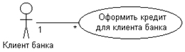
Fig.4. Communication link example
The inclusion relationship is used in situations where there is some piece of system behavior that is repeated in more than one use case. These relationships are typically used to model reusable functionality.
Extension relationships are used to describe changes in the normal behavior of a system. It allows a use case to use the functionality of another only when necessary.
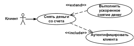
Fig.5. Example of inclusion and extension relationship
Through connection, generalizations show that several actors have common characteristics.
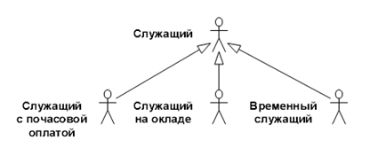
Fig.6. Generalization link example
Interaction diagrams
Interaction diagrams describe the behavior of interacting groups of objects. Typically, an interaction diagram covers the behavior of objects within only one use case. Such a diagram displays a number of objects and the messages that they exchange with each other.
A message is a means by which a sending object requests a recipient object to perform one of its operations.
An informative message is a message that provides the recipient object with some information to update its state.
A request message (interrogative) is a message that requests the release of some information about the recipient object.
An imperative message is a message that requests the recipient object to perform some action.
There are two types of interaction diagrams: sequence diagrams and collaboration diagrams.
How does nlp semantic analysis work?