Sound card Experienced users will surely remember the days when computers could only beep. Times are changing, and now it's hard to imagine a computer without the ability to play and record sound. The quality of playback / recording can vary, although in recent times it has ranged from normal to chic (we agree that these terms are somewhat unscientific, but understandable). The sound quality of a computer depends on two devices: sound card and acoustic (computer, multimedia) speakers.
A sound card (sound card, sound accelerator, “zvukovuha”) is a device that allows a computer to play and record sound information. The need for sound among computer users is so great that almost all motherboards manufactured today contain an integrated sound card (similar to an integrated video card). As a rule, the capabilities of the built-in sound card are enough to meet the needs of most users. If you are not an ardent music lover or a fan of complete immersion in a computer game (this is when walls shake from your shots, and neighbors call the police), then integrated sound will be enough for you and you do not have to buy a more powerful sound card, which is a separate expansion card
Sound card connectors and sockets
- Line-out (line output) - a stereo output to which active speakers or headphones are connected. On cheap video cards there is only one such output, but there are sound cards with two or more line outputs (if it is designed to connect more than two speakers). You may also encounter line outputs in the form of two mono jacks (labeled right and left). By the current standard, the line-out connector is usually made in lemon color (don't ask us why, we don't know). However, some manufacturers (apparently also not understanding why lemon) do not adhere to this rule. For example, one of the authors has this green connector, while the other has all black connectors. And the connectors of professional and even semi-professional sound cards can be gold-plated. Better focus on the line-out icon or read the instructions for the sound card if the icon is missing. In addition, this connector can be used to connect various musical equipment (for example, a tape recorder or a music center) to a computer to play music through the speakers of a tape recorder or center, as well as to record on them.
- Line-in (line input) - stereo input for connecting other playing devices. It is necessary if you are going to record sound from other devices on your computer. The Line-in connector is usually blue.
- Mic-in (microphone) - a monophonic connector that is used to connect simple microphones and then record voice (or other sounds) on a computer. This connector is usually red or pink. Most conventional sound cards have only these three connectors, but more advanced and expensive ones boast several additional ones.
- MIDI / gameport (joystick port) - a rectangular connector that allows you to connect a game device (joystick) or, for example, a synthesizer keyboard. This connector is usually yellow.
- Speaker-out / Subwoofer (output to speakers / subwoofer) - a stereo output, unlike Line-out, which has an amplifier. You can connect passive speakers (without an amplifier) or a subwoofer to this connector. Some users think that if you connect active speakers to this output, the signal will get better. However, it is not. As a result, the sound quality will surprise you unpleasantly. This connector is orange.
- S / PDIF (Sony / Philips Digital Interface Format) - a connector that can be located both on the outside of the sound card and on the board itself (that is, inside system block). It allows you to connect external audio devices, such as a DVD player or home theater system, to your computer. The signal through this connector is output in digital form, which eliminates the appearance of noise inherent in analog devices.
- To save space on the external panel, some sound cards have one special socket, to which an external device with several connectors is connected at once: S/PDIF, Line-in/out and MIDI. Do not be alarmed if you do not find familiar connectors, just look in the box from the sound card, somewhere there should be an additional device.
- CD-in (MPC-3 CD-in) - a special connector that allows you to transfer information from the CD drive to the audio card in analog format. If the sound card manufacturers followed all the rules, its color is black or white.
- MPC-3 Aux-in (external device input) - connector for connecting other devices (for example, a second CD drive). Looks very similar to CD-in.
- MPC-3 Modem-in/out (input-output for connecting a modem) - this connector is used to connect a modem. This connector is green. It's usually not necessary unless you're going to listen to the modem crackle through your speakers or plan to teleconference over the Internet.
- Connector for connecting different daughter boards - has the largest size. Very similar to an IDE (remember, like a hard drive?). Daughter boards connected to a sound card to expand its capabilities. This is used by professionals working with sound.
First, let's single out four more or less independent blocks:
- 1. Block digital recording / playback. Performs analog->digital and digital->analog conversions in program transfer mode or via DMA. The digital channel of most common cards (except GUS) is compatible with Sound Blaster Pro (8 bits, 44 kHz - mono, 22 kHz - stereo).
- 2. Synthesizer block. It is built either on the basis of OPL2 (YM3812) or OPL3 (YM262) FM synthesis chips, or on the basis of WT synthesis chips (GF1, WaveFront, EMU8000, etc.), or both. It works either under the control of a driver (FM, most WT) - a software implementation of MIDI, or under the control of its own processor - a hardware implementation. Almost all FM synthesizers are compatible with each other, various WT synthesizers are not.
- 3. MPU block. Receives/transmits data via an external MIDI interface connected to the MIDI/Joystick connector and the connector for daughter MIDI boards. Usually more or less compatible with the MPU-401 interface, but most often software support is required.
Sound cards contain the following elements.
- Converters - they are on each stereo channel: analog-to-digital (ADC) and digital-to-analog (DAC) (there are more converters on expensive cards). The ADC processes the analog signal coming from the line-in or microphone and converts it to digital. A DAC, on the other hand, converts the digital signal to analog and sends it to the line output. The quality of the sound received depends on the bit depth supported by the transducer.
- Clock generator - generates clock signals to the converters, thereby setting the speed of information processing (remember the concept of sampling rate). The most popular sound cards today have a frequency of 96 kHz.
- Processor - forms the analog sound that we hear from the speakers from the incoming MIDI commands. It is the processor that determines the capabilities of the sound card. It is the "connector" between the computer's central processing unit, the operating system and the music playback program. The sound card processor takes on quite a lot of sound processing work (partially offloading the CPU).
Important characteristics of sound cards Now let's look at the main characteristics of sound cards, which are useful to pay attention to when buying. Sound cards like most internal devices, are usually connected to the PCI slot on the motherboard.
- The indicator to which we have already drawn your attention is - sampling frequency(it is set by the clock frequency generator). The higher this frequency, the more accurately the sound is digitized, which has a positive effect on the sound quality.
- The next parameter is number of audio channels. If you intend to play sound through two speakers, then any sound card will do (provided that you are satisfied with the other characteristics). If you want to surround yourself with sound, you need a multi-channel sound card (5.1 or 7.1). Of course, you will have to purchase the appropriate set of speakers. By the way, most sound cards built into modern motherboards contain six audio channels (5.1).
- Value signal-to-noise ratio(S/N) is measured in decibels. The higher the value of this value, the better. We advise you not to be interested in cards with S / N below 90 dB.
- Another characteristic is supported sample size. "Sample size" shows how much information each sound describes, and therefore sets maximum amount possible sound options. This applies to those who are interested in the possibilities of MIDI.
If you are interested in high-quality sound, we also recommend choosing a sound card with good hardware acceleration. Now most high-quality (and, mind you, inexpensive) sound cards support 3D mode.
Several years have passed since the first time I "opened the entrance" to the sound card according to the article by O. Shmelev "Computer measuring complex". Very convenient and, I would even say, a necessary thing when setting up and checking all kinds of audio paths using programs like SpectraLab or . See the constant levels, check the frequency response, and just write a temporary file to memory for later comparison or careful viewing of the signals - very often I have to do it ... But every time I use this sound card, I think that I had to move the input connector to the front panel system manager, put the switches "input divider by 10" (or even by 100) and "open / closed input". That is, to get closer to the usual conveniences of an oscilloscope.
And then an old PCI-th sound card VIA TREMOR accidentally fell into the hands. Well, that's it, I think, now I'll make the input block for sure. I will place all the additional details in the case from the old CD drive, put switches on its face and connect it all to the sound card with a piece of signal cable from the monitor - it has a lot of conductors, it is shielded, and some conductors even twice - everything should work out ...
Started to screw drive...
Yes, first, perhaps, it is necessary to explain why something should be redone in the sound card, when it seems that there is something complicated there - remove the capacitors at the input, and you will get " open entrance". But the fact is that there is a constant voltage (about 2.5 volts) on the input legs of the codec, which it needs to work. If it is equal to the internal reference potential, relative to which the analog-to-digital converter tracks changes in the input signal, then the horizontal line drawn by the oscilloscope of the program will go along the zero mark of the scale. If this voltage is reduced, say, by 1 V, then the horizontal line of the oscilloscope will float down by 1 V. And it turns out that if you simply remove the capacitor from the input circuit, then the connected signal source, if it does not have a capacitor at its output, will sag it's a constant voltage. Therefore, it is necessary to add additional chains in order to “bypass” this obstacle. The task, in general, is simple and is solved at the level of the initial study of circuitry using operational amplifiers ( fig.1) . If the output of resistor R2, which is lower according to the circuit, is grounded, then when a signal of 0.25 V is applied to the input of the op-amp, the output level is 0.25 * (1 + (R3 / R2). If, with the same resistances of resistors R2 and R3 to the lower terminal of the resistor R2 apply a constant negative voltage of 2.5 V, then at the output of the op-amp we will get a constant positive voltage of 2.5 V. If the value of the resistor R1 does not exceed 100 kOhm, then when using operational amplifiers in this circuit general purpose with a sufficiently large input resistance, we can say that the input resistance of the stage is equal to the resistance of the resistor R1.
The final circuit of the input block turned out to be small. Half of the space on the board is occupied by a power stabilizer and filters. You can't do without them here - the key power converters of the computer and processor create a large electromagnetic "background" that is induced on any conductor located in the system unit case, whether it is supply or signal.
But let's start in order.
So, the drive began to smoke. I sawed off the extra plastic - there is a lot of free space ... I figured out what and how it would be attached ... According to the scheme ( fig.2) signals from the input connector J are fed to the switches S1 and S2, switching the opening or closing of the inputs. When the switches are opened, the lower cutoff frequency at -3 dB level becomes about 1.2 Hz if the 10 dividers (S3 and S4) are not turned on, and about 3 Hz when these dividers are turned on. All switches are separate, i.e. not paired - this allows you to select different modes in different channels. The input impedance of the block depends on whether the dividers by 10 are enabled or not. When they are open, Rinput is approximately equal to 86 kOhm (R1 + R3 + R7 or R2 + R4 + R8), and when closed - 37 kOhm (R1 + R3 + R5 or R2 + R4 + R6). Of course, this part of the circuit can be done in a different way, for example, as shown in figure 3- so that when the divider is turned on by 10, the input resistance also increases by 10 times (approximately) - up to 870 kOhm. But at the same time, it is necessary to take into account the change in the cutoff frequency of the low-pass filter formed by the resistors R1R5 and the total capacitance, consisting of the capacitance of the limiting diodes, the input capacitance of the operational amplifier and the mounting capacitance. Here it is important not so much that the frequencies begin to “fall over”, but that the phase shift of the signal begins already from 3-5 kHz, and this is already critical for some phase measurements. When calculating these circuits, it is convenient to use the program (the file for the calculation is attached as an attachment to the article).

Fig.3

Let's go back to the diagram figure 2. Diodes VD1 ... VD12 protect the op-amp from large input signals, limiting them in amplitude to a level of 1.7-2.2 volts. Depending on the input sensitivity of the sound card, it may be necessary to install chains of a smaller number of series diodes.
As you can see from the diagram, the resistors that provide the above input resistances of the block are also dividers of the input signal even without switching on S3 and S4. This is done specifically to compensate for the gain caused by the difference in the resistances of the resistors in the feedback of the operational amplifiers (R2 and R3 by numbering figure 1). This happens due to the fact that R2 in a real circuit according to figure 2 consists of several - R9, R11, R12, R16 and R19, which perform the function of forming a voltage of +2.5 V at the output of the block and allowing you to change its level in the range from 2.4 to 2.6 V. This is necessary to correct the drift of the output voltage +2.5 V, which appears with the heating of the elements both in the input block and in the sound card codec. Also, when working in the SpectraPLUS program, sometimes there is a need to shift one of the graphs vertically, which can be done by turning one of the sliders of the resistors R11 and R14 installed on the front panel of the unit.
At the outputs of the op-amp, there are dividers R21R23 and R22R24, attenuating the signal by about 3.5 dB. This is done in order to attenuate the noise that occurs in the op-amp. You can not do this and remove R21 and R22, but then you need to increase the resistances of resistors R19 and R20 to about 6.8 kOhm so that the unit output has a constant voltage of +2.5 V. Resistors R23 and R24 are not installed on the board input block, and in the sound card at the input of the codec. This reduces interference on the signal conductors of the connecting cable.
The -5 V stabilizer is a standard 7905 microcircuit. You can also supply a low-current 79L05. 12 V voltage filtering is performed on LRC elements. It is desirable to use all electrolytic capacitors with a capacitance of more than 1000 μF, and chokes with an inductance of more than 47 μH, but within reasonable limits - otherwise, with a large inductance, impulse noise will pass through the choke along the interturn capacitance.
All parts, except for the input connector J, switches S1 ... S4, capacitors C1 and C2 and resistors R11, R13 are installed on a foil single-sided printed circuit board 110x60 mm in size ( fig.4) (the board file in the program format is in the attachment to the article). Board mounting is surface, no holes need to be drilled, even for output parts. All diodes are KD522 (or KD521) with almost completely bitten off leads. Resistors R1, R2, R5 and R6 are MLTs, with one terminal soldered to the printed track, and wires coming from the switch are soldered to the other. All other resistors and all ceramic capacitors are smd 0805. All electrolytic capacitors are on the board and glued to it with hot glue. Chokes in filters can be used both domestic output and imported. Operational amplifiers - KR140UD608, can be replaced with any other general-purpose ones, the main thing is that they have an input impedance of more than 300-400 kOhm.

You can set up the assembled board with soldered variable resistors on the table by soldering resistors R23 and R24 and applying bipolar voltage to the board from a laboratory power source. After making sure that there is power at the outputs of the op-amp and -5 V, it is necessary to adjust the level of +2.5 V with resistors R12R14 at the connection points of the output dividers R21R23 and R22R24. If something is wrong, pick up the resistance R19 and R20. Then you need to check the input circuits, applying AC and DC voltages to the input and monitoring them at the output of the op-amp. If you want to have a different division factor, you need to select the resistances of resistors R5 and R6.
Switches S1 ... S4 brand MT1 can be replaced by P1T-1-1. They are fixed on a metal plate of a suitable size ( fig.5). The plate is connected with a short conductor to the body of the CD drive. Capacitors C1 and C2 - K73-17 with a capacity of 1.5 microfarads for a voltage of 160 V are soldered directly to the terminals S1 and S2. The input jack uses the drive's native CD (3.5mm). Resistors R11 and R14 are taken from old monitor boards. Soldered into a small handkerchief, which is inserted into pre-cut slots in the front of the plastic frame of the drive ( fig.6).

Fig.6

A circuit board made of foil textolite was cut to fit the size of the plastic frame ( fig.7). To make it stand in place, grooves are cut in it and holes are drilled. You can, of course, make a board not from textolite, but in order for it to be properly fastened, its thickness should be about 1.5 mm.

The input block board is installed on the mounting bracket on brass racks from motherboards ( fig.8). Getinax washers are placed under the head of the fixing screws so that the “ground” of the board is not galvanically connected to the drive case, but through it to the system unit case. If this is not done, then a “ground loop” will be obtained through the connecting cable, on which interference from the electromagnetic pulses of the converters will be induced.

The switching diagram of the input unit with a sound card is shown in figure 9. The connection of the "grounds" of both devices occurs only on one wire - light brown.

On drawings 10, 11
and 12
shows a general view and a power connector mounted on the rear wall of the plastic frame. The connector is taken from an old video card - sawn out directly from a piece of a printed circuit board. All "ground" conductors connecting some of the connector legs to each other are cut. This is all done for the same reason - the "grounds" must be connected in one place on the sound card. The printed circuit board shown is slightly different from the one shown above in the text - in the photo there is an option with +/-5V op-amp power supply and some differences in additional SMD components, but this is not important.

Fig.11

Fig.12

As I said, the sound card used was an old one - VIA TREMOR with VT1617A codec. Its sensitivity is about 1 V (rms) - then it starts to be heavily overloaded. The card turned out to be very noisy in the computer used ( fig.13) and required a little refinement related to power filtering.

First, I cut the power tracks of the VT1723 and VT1617 microcircuits (red marks, respectively, on the left and right along figure 14):

Then, by surface mounting, right on the board, I soldered the CLC filter for VT1723 and the stabilizer for VT1617 ( fig.15, fig.16 and fig.17). Left on Figure 15 the letter "A" and the numbers following it are the contact numbers PCI bus from the "A" side.

Fig.16

Fig.17

On Figure 17 you can see the conductor coming from the left leg of the MLT resistor to pin 2 of the PCI bus. This is a connection to +12 V. A thin MGTF wire is neatly soldered to the very edge of the contact track. If you get a large drop of solder, then it can interfere with installing the card, resting against the plastic housing of the connector. On Figure 18 the place of soldering the wire to the -12 V contact is shown in more detail.

If, suddenly, the card on the bus does not have +/- 12 V contacts, then they can be made by cutting out copper foil and gluing it with BF glue. So I had to do this on the C-MEDIA card for -12 V power supply. More than three years have passed, now it is already in the third computer and has withstood several dozen “twitchings” during this time.
On Figure 19 general photo of the modified VIA TREMOR map. A piece of textolite fixed with two screws is visible, to which the cable is rigidly fixed. Both surfaces of this mounting plate are grounded, and on one of them there are cut out areas to which the wires are soldered. The input capacitors at the line input are soldered out, and the MGTF wires are soldered to the patches of the tracks that go to the codec, going to the signal (red and green) wires of the cable. All braids, shields and free conductors of the cable are soldered to the "ground" on the mounting plate.

After all these executions and the installation of additional electrolytic capacitors for power supply in different places on the sound card, the noise became less ( fig.20), but, unfortunately, there is still an interference with a frequency of 46.88 Hz and its odd harmonics. They, of course, have almost halved, but this is not the result that we would like to get.

How this interference is formed, has not yet figured out. But, given that its level is less than 100 μV (rms), and at frequencies above 1 kHz its harmonics are below 110 dB, it is quite possible not to take it into account, especially in the oscilloscope mode. Of course, I could not resist and looked at what she was like. On figure 21 it can be seen that the interference is digital in nature, occurs synchronously in both channels and has approximately the same level - most likely, it is induced from the processor power converter. It helped to install resistors R23R24 3.9 kOhm from the codec inputs to ground (when working together with the input block). The fundamental frequency level dropped to -90 dB, and the harmonics above the 5th were attenuated almost to the level of noise. Soldering additional electrolytic capacitors for power supply in the sound card and ceramic ones for powering the processor and in the power supply did not bring tangible results. Shielding the card with soft tin and "decoupling" from the computer case was also unsuccessful.

The graph shows a gradual increase in potential in a positive direction. In fact, this offset is associated with the instability of the power supply of the op-amp and it is not smooth, but chaotic and is in the frequency range from 0 to 10 Hz. But the level of these low-frequency fluctuations is quite small - no more than 1-2 mV, and, if desired, can be easily treated by installing op-amp supply voltage stabilizers (this version of the printed circuit board is also included).
On Figure 22 interference from the previous figure, but increased in time:

When used in conjunction with the input block of another sound card (based on the CMI8738 codec), this interference is absent. It is possible that the VIA card has an incorrectly set “ground” - everything is very primitive there ...
Now about setting parameters in the SpectraPLUS program and its calibration. They say that the network has a description of how to do it correctly, but I didn’t manage to “intersect” with him, so I had to remember metrology. And as far as I remember, in order to use the device as a measuring device, it is necessary to link the program scales to the actually present signal levels at the input (here we consider the sound card and the input block as a whole).
An exemplary sinusoidal signal with a frequency of 1 kHz was taken from a G3-118 low-frequency generator. The level was controlled by a VR-11A voltmeter and an oscilloscope. The connection diagram is shown on figure 23.

First in the master volume menu Windows programs we find the desired sound card and in the settings select it to work as an input and put a tick only in front of the line “Lin. input". The slider-regulator responsible for sensitivity is set to the middle position for the time being.
Andrey Goltsov, r9o-11, Iskitim, spring 2014.
List of radio elements
| Designation | Type | Denomination | Quantity | Note | Shop | My notepad | |
|---|---|---|---|---|---|---|---|
| Figure 2 | |||||||
| OP1, OP2 | Operational amplifier | KR140UD608 | 2 | To notepad | |||
| VR1 | Linear Regulator | LM79L05 | 1 | To notepad | |||
| VD1-VD12 | Diode | KD522A | 12 | To notepad | |||
| R1, R2 | Resistor | 33 kOhm | 2 | MLT-0.25 | To notepad | ||
| R3, R4, R21, R22 | Resistor SMD 0805 | 2.2 kOhm | 4 | R3, R4 pick up (see text) | |||
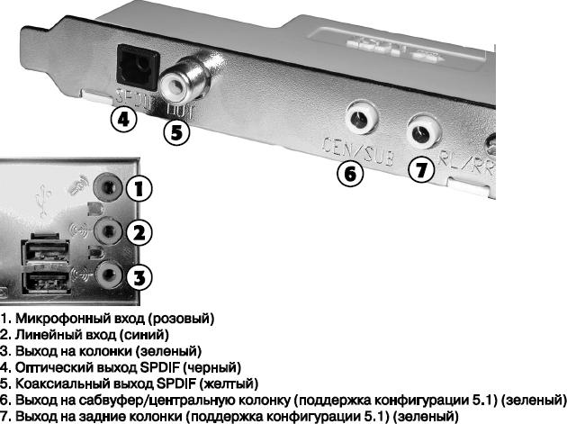
Majority sound cards have connectors the same amount. Through these miniature (1/8 inch) connectors, signals are fed from the board to speakers, headphones and stereo system inputs; a microphone, CD player and tape recorder are connected to the same connectors. Laptops are usually equipped with only two connectors: line-in and line-out. Some high-end audio adapters additionally include connectors for connecting 5.1 and 7.1 surround and digital audio devices.
The figure shows four types of connectors that must be installed on your sound card. The second picture shows the standard sound card connectors, which are usually present on the back motherboard with integrated sound.
Many modern systems with integrated audio also use another method: installing a universal jack that supports version AC "97 of the 2.3 standard. When an audio device is connected to this jack, the driver opens a dialog box asking for the type of equipment connected: microphone, headphones, speaker system, etc. The driver automatically assigns a signal to this jack that supports this device, in this case, even if you insert the plug into the wrong jack (i.e. not according to the color coding), the driver will still route the correct signal to it.This function is sometimes called automatic recognition.
Advice!
In order not to confuse the recognition function, insert the device plugs in sequence, then determine the device type and only then insert the next plug.
Characteristics of sound card connectors
The following are sound card connectors:
- Line output (light green). The signal from this jack can be sent to external devices- speakers, headphones or stereo input. In the latter case, the signal can be further amplified. As shown in the previous figure, in some systems light green markings are also used for certain surround sound connectors, so take a closer look at the additional icons next to the connector or take a look at the documentation.
- Line input (blue). This input jack is used when mixing audio from an external audio system and/or recording it to HDD. Some audio adapters (notably the Creative Labs Sound Blaster XFi Xtreme Gamer shown in Figure 1) use a multi-purpose jack (FlaxiveJack in this example) to support various combinations of line-in, microphone connection, and digital optical input/output (see documentation for adapter).
- Connector for rear speakers and headphones (no standard color). Virtually all modern audio adapters and desktop systems with integrated audio include rear, center, and subwoofer connectors that are used in 5.1 surround sound systems and above. Systems that support the 5.1 standard have three connectors: one for the front (stereo), one for the rear (stereo), and a third for the center and subwoofer (subwoofer) speakers. 6.1 and 7.1 compatible systems may include an auxiliary jack or remap the rear and center/subwoofer speaker jacks to provide additional output. Depending on the specific driver, surround sound may require an installer provided by the manufacturer. True, in some cases, switching to surround sound mode in the sound settings in operating system turns out to be enough.
- Microphone input (pink). To that sound card connector connects a microphone to record voice or other sounds on the disc. Microphone recording is monaural. To improve signal quality, many sound cards use automatic gain control (AGC). The input signal level is maintained constant and optimal for conversion. For recording, it is best to use an electrodynamic or condenser microphone, designed for a load impedance of 600 ohms to 10 kOhms. In some cheap sound cards, the microphone is connected to the line-in.
Note!
If only one line-out connector is available, you must carefully select the volume levels for your sound card and active speakers to get the best sound quality. Avoid loudspeakers with fixed gain levels.
In addition to external connectors, some older audio adapters have one 4-pin connector directly on the board - a special cable connects it to the CD drive. This cable allows you to directly transfer audio from music CDs directly to the adapter for playback in acoustic systems. This type of connector is sometimes the same as a similar connector on a CD-ROM drive.
Music CDs are played in one of the following ways: the sound is played in either analog or digital form. Analogue playback is performed using an analog audio cable connecting the drive to the sound card. This cable does not carry data to the system bus that is read from the CD; it connects the analog audio output of the CD-ROM drive directly to the audio amplifier located on the sound card. In many cases, playing music CDs or listening to the soundtrack found in many computer games requires you to connect the CD-ROM drive to your sound card using an audio cable.
Modern sound cards(including integrated ones) support both digital playback and analog direct connection. To determine if digital playback is supported, open the Optical Disc Drive Properties dialog box. To do this, in the Manager Windows devices click right click mouse on the CD-ROM device element and select in context menu item Properties. Pay attention to the Use digital playback check box on the Properties tab: if it is not available (that is, it does not allow you to check), then the card or device does not support digital playback.
Digitized audio allows you to use various storage media to play music CDs. In fact, the sound card has only one analog connector, so if there are several drives on optical discs only one of them, connected to the sound card with an analog cable, can play music CDs. To play audio CDs on multiple drives, you will need to activate the digital output on those drives or purchase a Y-shaped audio cable. Digital output or drive connection with analog audio cable allows you to play music CDs on any CD-ROM/DVD drive.
Note!
Modern versions of many audio players, such as Windows Media Player, can play sound without the need for a two-wire digital cable that connects the CD-ROM drive to the sound card. Instead, these programs simply read the audio tracks from the CD and digitize them on the fly.
- Next >
Sound card connectors: Card line output (green) – the signal from this connector can be fed to external devices – speakers, headphones Stereo system inputs Some sound cards have 2 output jacks: one for the left channel signal, the other for the right one. Board Line In (blue) - This input is used when mixing or recording audio from an external audio system. Microphone or mono input (pink) - Connect a microphone to this jack to record voice or other sounds on a disc. Microphone recording is monaural. For recording, it is best to use an electrodynamic or condensate microphone, designed for a load impedance of 600 ohms to 10 k ohms. In some cheap sound cards, the microphone is connected to the line-in.

Sound card connectors (continued): Game port connector, or MIDI connector (yellow) - A 15-pin D-connector is used to connect the joystick. Its 2 pins can be used to control a MIDI device, such as a keyboard synthesizer (In this case, you need to purchase a Y-cable). Some of the latest audio adapters and built-in sound systems do not have this connector as the newer generation of gamepads plug into the USB connector.


Additional sound card connectors: SPDIF In/Out (SP/DIF) - This connector (Sony/Philips Digital Interface) is used to transfer digital audio signals between devices without conversion to analog. CD SPDIF - this connector is designed to connect a CDROM to a sound card using the SPDIF interface.

Additional sound card connectors: TAD input - a connector for connecting modems with support for an answering machine (Telephone Answering Device) to the sound card. DIN Digital Output - This connector is for connecting multi-channel digital speakers. Aux input - provides connection to the sound card of other signal sources, such as a TV tuner. I2S input - allows you to connect the digital output of external sources, such as DVD, to the sound card.

Additional sound card connectors: USB port– allows you to connect your sound card to a USB speaker system, game controllers and other USB devices. Can be used as USB 1.1 and USB 2.0. IEEE-1394 – digital video cameras, scanners, hard disks and other devices. The SB1394 connector on the Sound Blaster Audigy allows you to connect both IEEE1394 devices and devices that support Creative Labs' new SB1394 format. Additional connectors are usually located directly on the sound card or connected to an external unit or daughter card.

Amplitude-frequency response (AFC)- dependence of the oscillation amplitude at the output of the sound card (output to the speakers) on the frequency of the input analog signal with a constant input signal amplitude. The frequency response shows how the individual frequency components of an analog signal are transmitted through the sound card, and allows you to evaluate the distortion of its spectrum.
Signal to noise ratio- represents the ratio of the values (in decibels) of the undistorted maximum signal at the output of the sound card to the level of electronic noise that occurs in its own electrical diagrams fees. Since people perceive noise at different frequencies differently, a standard has been developed that takes into account annoying noise levels. The higher this ratio, the better the sound system. Reducing this parameter to 75 dB is unacceptable.
Total harmonic distortion- reflects the effect of distortions introduced by individual channels of sound amplification and noise generated by the board itself. It is measured as a percentage of the undistorted output level. A device with a level of non-linear distortion of more than 0.1% cannot be considered of high quality. Nonlinear distortions are more manifested in the form of a distortion in the quality of the reproduced sound (wheezing).
dynamic range. The difference in decibels between the max and min signals that the board can skip. In an ideal digital audio system, the dynamic range should be close to 98 dB.
Each sound is characterized by frequency and intensity (loudness). Frequency (tone) is the number of sound vibrations per second; it is measured in hertz (Hz). A cycle (period) is one closed movement of the oscillation source (back and forth). The higher the frequency, the higher the tone.
The human ear perceives only a small range of frequencies. Very few hear sounds below 16 Hz and above 20 kHz (1 kHz = 1000 Hz). The frequency of the sound of the lowest note on the piano is 27 Hz, and the highest is just over 4 kHz. The highest audio frequency that FM broadcasting stations can transmit is 15 kHz.
Simply amazing compression ratios in MP3 format in relation to ordinary WAV files with the quality of a music CD are precisely explained by the fact that from the wave image sound track all frequencies that are not audible to the human ear are “cut out”.
The loudness of the sound is determined by the amplitude of the vibrations. The amplitude of sound vibrations depends, first of all, on the power of their source. For example, a piano string sounds soft when the key is struck lightly, because its range of vibration is small. If you hit the key harder, then the amplitude of the vibrations of the string will increase. Sound loudness is measured in decibels (dB). The rustle of leaves, for example, has a loudness of about 20dB, normal street noise is about 70dB, and close thunder is 120dB.
AT modern computers Hardware support for sound can be implemented in one of the following forms:
sound card installed in the PCI bus slot – discrete sound cards;
AC "97 chip on the motherboard, manufactured by Crystal, Analog Devices, Sigmatel, ESS, Realtek, etc.
sound devices integrated into the main chipset system board; low-cost chipsets with similar capabilities include products from Intel, SiS, AOpen, and VIA Technologies.
· External connected via USB.
The general rule here is this: the more expensive the motherboard, the better the sound chip soldered onto it.
Most sound cards have the same connectors. Through these miniature (1/8 inch) connectors, signals are fed from the board to speakers, headphones and stereo system inputs; a microphone, CD player and tape recorder are connected to the same connectors. Laptops are usually equipped with only two connectors: line-in and line-out. Some high-end audio adapters additionally include connectors for connecting 5.1 and 7.1 surround and digital audio devices.
The figure shows four types of connectors that must be installed on your sound card. And the second picture shows the standard connectors that are usually found on the back of a motherboard with integrated audio.

Listed below are the connectors that a sound card typically contains and their color coding.
· Line output (light green). The signal from this connector can be fed to external devices - speakers, headphones or stereo system input. In the latter case, the signal can be further amplified. As shown in the previous figure, in some systems light green markings are also used for certain surround sound connectors, so take a closer look at the additional icons next to the connector or take a look at the documentation.
· Line in (blue). This input jack is used when mixing audio from an external audio system and/or recording it to the hard disk. Some audio adapters (notably the Creative Labs Sound Blaster XFi Xtreme Gamer shown in Figure 1) use a multi-purpose jack (FlaxiveJack in this example) to support various combinations of line-in, microphone connection, and digital optical input/output (see documentation for adapter).
· Rear speaker and headphone jack(no standard color). Virtually all modern audio adapters and desktop systems with integrated audio include rear, center, and subwoofer connectors that are used in 5.1 surround sound systems and above. Systems that support the 5.1 standard have three connectors: one for the front (stereo), one for the rear (stereo), and a third for the center and subwoofer (subwoofer) speakers. 6.1 and 7.1 compatible systems may include an auxiliary jack or remap the rear and center/subwoofer speaker jacks to provide additional output. Depending on the specific driver, surround sound may require an installer provided by the manufacturer. True, in some cases, switching to surround sound mode in the sound settings in the operating system is quite enough.
· Microphone input (pink). Connect a microphone to this jack to record voice or other sounds on the disc. Microphone recording is monaural. To improve signal quality, many sound cards use automatic gain control (AGC). The input signal level is maintained constant and optimal for conversion. For recording, it is best to use an electrodynamic or condenser microphone, designed for a load impedance of 600 ohms to 10 kOhms. In some cheap sound cards, the microphone is connected to the line-in.
In addition to external connectors, some older audio adapters have one 4-pin connector directly on the board - a special cable connects it to the CD drive. This cable transfers sound from music CDs directly to your speaker adapter. This type of connector is sometimes the same as a similar connector on a CD-ROM drive.
Music CDs are played in one of the following ways: the sound is played in either analog or digital form. Analogue playback is performed using an analog audio cable connecting the drive to the sound card. This cable does not carry data to the system bus that is read from the CD; it connects the analog audio output of the CD-ROM drive directly to the audio amplifier located on the sound card. In many cases, playing music CDs or listening to the soundtrack found in many computer games requires you to connect the CD-ROM drive to your sound card using an audio cable.
Modern audio adapters (including integrated ones) support both digital playback and direct analog connection. To determine if digital playback is supported, open the Optical Disc Drive Properties dialog box. To do this, in the Windows Device Manager, right-click on the CD-ROM device element and select Properties from the context menu. Pay attention to the Use digital playback check box on the Properties tab: if it is not available (that is, it does not allow you to check), then the card or device does not support digital playback.
Digitized audio allows you to use various storage media to play music CDs. In fact, the sound card has only one analog connector, so if you have multiple optical disc drives, only one of them, connected to the sound card with an analog cable, can play music CDs. To play audio CDs on multiple drives, you will need to activate the digital output on those drives or purchase a Y-shaped audio cable. Digital output or drive connection with analog audio cable allows you to play music CDs on any CD-ROM/DVD drive.