The lucky owners of a country house or dacha have more than once had to face a problem: in areas remote from the city there is simply no connection so that you can use a mobile phone or watch TV. If modern Cell phones are already equipped with powerful hidden antennas for receiving signals, then the signal for watching TV is more difficult. The only solution is external antenna. Moreover, you don’t have to run to the store to buy expensive equipment - you can easily make an antenna for your dacha (using a GSM signal) with your own hands!
If your dacha already has a weak signal and your TV has poor reception of 1-2 channels, then you can improve the quality of reception in a matter of minutes. First, you should understand that the stations sending the signal are located at a distance from your dacha. And your TV is now receiving a random signal that was not directed to a specific receiver. In order for the signal to become better, you need an antenna (receiver) that will transmit the signal directly to the TV.
An antenna can be made either from an old antenna or from things that are completely unsuitable at first glance - scrap materials.
In the first option, we’ll look at how to make a classic antenna for a summer house with your own hands
1) Wire. You should choose a high-quality conductor based on the following calculation: 1.5-2 meters per antenna, 5-6 meters (depending on your interior) at the distance from the antenna to the TV. Let's assume that you have chosen a wire whose diameter is 1.5 mm.
2) The outer part of the antenna. Made from prepared wire. 1-1.5 meters need to be twisted into a ring, the diameter of which will be from 356 mm. up to 450 mm.
3) Internal part of the antenna. It is necessary to make a second ring from wire, correspondingly smaller than the first (about 180 mm).
4) The finished rings - this is the basis of the future antenna - need to be fixed on a small piece of plywood. Instead of plywood, you can use any suitable piece of wood. The tree should not overlap the rings and should not dangle so that the entire antenna is clearly fixed to the roof.
5) The finished structure must be directed in rings in the direction of the signal source. No doubt the signal will be strong towards the city. At this stage, ask for help: you need to turn the antenna in different directions and check where the signal will be better. Once you find the best option, your antenna is finally ready!
Making an antenna from beer cans
There are many ways to make a simple and high-quality (for a high-quality signal) television antenna for your summer cottage. We looked at a way to create a “classical” antenna, but there are also non-standard solutions. For example, you can quickly make an antenna from old tin cans (Coca-Cola or beer). Such an antenna is in no way inferior in characteristics to store-bought innovations, plus it will help the owner of the dacha save money.
To create an antenna you will need a couple of 0.5 liter tin cans, rosin, tin, some electrical tape, simple tape, a clothes hanger (must be plastic!) and 5-6 meters TV cable(which, by the way, does not have to be new!).

- To the first can you need to solder a TV cable (braided, peeled to 15-20 mm), and to the other - the central core (of the same cable). It will be easier to dip the soldering iron in tin and rosin, and then tin the wire. Conductors should be insulated with electrical tape!
- Attach the jars to the hanger, to its bottom.
- Connect the plug to one side of the cable
- Connect the plug to the TV. The antenna is ready!
Such an antenna can also catch the “meter” range if you use cans with a volume of 1.0 liter rather than 0.5 liters. If in the first case it was necessary to rotate the antenna in order to “catch” a good signal, then in the case of tin cans you should change the distance between them (the cans) on the hanger. Place the antenna itself near a window or balcony.
Thus, there are many ways to make an antenna for your dacha with your own hands and provide yourself and your loved ones with a pleasant viewing of television programs in the fresh air. “Homemade” antennas are in no way inferior to store-bought ones and can become a 100% substitute for them (especially since it will be easier and cheaper to make a new antenna than to buy a store-bought one in case of a breakdown)!
In the days of huge tube TVs, a good antenna for high-quality analogue television reception was in short supply. Those that could be bought in stores were not of high quality. Therefore, people made UHF television antennas with their own hands. Today, many are interested in homemade devices. And even when digital technologies are everywhere, this interest does not fade.
Digital era
This era also affected television. Today T2 broadcasting is developing especially widely. It has its own characteristics. In those places where the signal level is slightly higher than the interference, fairly high-quality reception is obtained. There is simply no further signal. A digital signal does not care about interference, however, in a situation where there is a cable mismatch or various phase distortions almost anywhere in the transmitting or receiving path, the picture can appear in squares even with a strong signal level.
There have been other changes in modern television. Thus, all broadcasting is carried out in the UHF range, the transmitters have good coverage. The conditions under which radio waves travel through cities have changed greatly.
Antenna parameters
Before starting manufacturing, you need to determine some parameters of these structures. They, of course, require in-depth knowledge in various fields of mathematics, as well as the laws of electrodynamics.
So, the gain is the ratio of the power at the input of the reference system to the power at the input of the antenna used. All this will work if each of the antennas creates values of intensity and flux density with the same parameters. The value of this coefficient is dimensionless.
Directional coefficient is the ratio of the field strength created by the antenna to the field strength in any direction.

It is necessary to remember that parameters such as KU and LPC are not interrelated. There is a UHF antenna for digital TV, which has a very high directivity. However, its gain is small. These structures are directed into the distance. Highly directional designs also exist. Here it comes in combination with a very powerful gain level.
Today you don’t have to look for formulas, but use special programs. They already take into account all the necessary parameters. All you have to do is enter some conditions - and you will receive a complete calculation of the UHF antenna, so that you can then assemble it.
Manufacturing nuances
Any structural element in which signal currents flow must be connected using a soldering iron or welding machine. Such a node, if it is located in the open air, suffers from contact failure. As a result, various antenna parameters and reception levels can become significantly worse.
This is especially true for points with zero potentials. According to experts, voltage can be observed in them, as well as current antinodes. To be more precise, this is the maximum current value. Is it available at zero voltages? No wonder.
Such places are best made of solid metal. Creeping currents are unlikely to affect the picture if the connections are made by welding. However, due to their presence, the signal may disappear.
How and what to solder with?
It is not very easy to make a UHF antenna with your own hands. This involves working with a soldering iron. Modern television cable manufacturers no longer make it copper. Now there is an inexpensive alloy that is resistant to corrosion. These materials are difficult to solder. And if you heat them long enough, there is a risk of burning out the cable.

Experts recommend using low-power soldering irons, low-melting solders, and fluxes. Don't skimp on paste when soldering. Solder will lie correctly only if it is under a layer of boiling flux.
Catching T2
In order to enjoy digital television, it is enough to purchase a special tuner. But it does not have a built-in antenna. And those that are offered as digital specials are too expensive and pointless.
Now we will learn how to catch T2 on a completely homemade design. A homemade UHF antenna is simple, cheap, and of high quality. Try it yourself.
The simplest antenna
To assemble this structure, you don’t even need to go to the store. To make it, a regular antenna cable is enough. You need 530 mm of wire for the ring and 175 mm from which the loop will be made.

The TV antenna itself is a ring of cable. The ends need to be stripped and then connected to the loop. And to the latter you need to solder a cable that connects to the T2 tuner. So, on the ring, the screen and the central core are connected to the loop screens. At the latter, the central cores are also connected. And the cable to the tuner is soldered as standard to the screen and central core.
So we got a UHF antenna, made with our own hands. Its design turned out to be very cheap and practical. And it works no worse than expensive store-bought options. It needs to be fixed to plywood or plexiglass. Construction clamps are perfect for this.
"People's" antenna
This design is a disk made of aluminum. The outer diameter of the element should be 365 mm, and the inner diameter should be 170 mm. The disc should have a thickness of 1 mm. First you need to make a cut in the disk (10 mm wide). In the place where the cut was made, a printed circuit board made of PCB should be installed. It should be 1 mm thick.

The board must have holes for M3 screws. The board must be glued to the disk. Then you need to solder the cable leads to it. The central core should be soldered to one side of the disk, the screen to the other. As for quality, such a TV antenna will receive better with two disks, especially if it is located far from the television repeater.
Universal antenna
Nothing supernatural will be used to make this design. We will make it from various available materials. However, even though it is homemade, it will work perfectly in the entire decimeter range. So, this UHF antenna, quickly made with your own hands, is in no way inferior to store-bought, more expensive designs. It will be completely enough to take T2.

So, to assemble this structure, you will need empty cans of canned food or beer. You need 2 cans with a diameter of 7.5 cm. The length of each is 9.5 cm. You also need to stock up on strips of textolite or getinax, always with foil.
Our cans need to be connected to PCB strips using a soldering iron. The plate of this material that will connect the containers at the top should have a continuous coating of copper foil. The foil on the bottom plate should be cut. This is done for convenient cable connection.
It is necessary to assemble the structure in such a way that the total length is not less than 25 cm. This antenna (UHF range) is a broadband symmetrical vibrator. Due to its surface area, it has large gain factors.
If suddenly you cannot find suitable jars, then you can use containers with a smaller diameter. However, then the foil will have to be cut on the upper connecting plate as well.
"Beer" antenna
Do you like to drink beer? Don't throw away cans. You can make a good antenna out of them. To do this, you need to attach two beer cans to any dielectric material.
First you need to choose a suitable cable, and then bring it to mind. To do this, the cable must be stripped. You will see shielding foil. There will be a protective layer underneath. But under it you can directly observe the cable.
For our antenna, you need to strip the top layer of this wire by about 10 cm. The foil needs to be carefully twisted so that you end up with a branch. The protective layer for the central core needs to be stripped to 1 cm.
On the other side, you need to solder a plug for the TV onto the cable. If you were a cable network subscriber, then you don’t even have to purchase this part and cable separately.
Now about the cans. It is advisable to use 1 liter beer containers. However, good German beer in such cans is expensive, and domestic beer is not sold.

Banks must be uncorked very carefully. Then you need to empty the container of its contents, and then dry it well. Next, use a self-tapping screw to connect our screen on the cable and the can. You need to screw the central core to the second one.
For higher image quality, it is better to connect the containers and cable using a splice.
The cans must be secured to some kind of dielectric material. It is necessary to take into account that they should be located on the same straight line. The distance between them depends on the capacity. All this can only be determined empirically.
Zigzag
The UHF zigzag antenna has the simplest possible design. The part itself is broadband. Its design allows for various deviations from the original design parameters. In this case, its electrical parameters will be almost unchanged.
Its input impedance in a certain range depends on the size of the conductors that will form the basis of the fabric. There is a dependency here. The greater the width or thickness of the conductors, the better the antenna will be matched with the feeder. In general, any conductors can be used to make the fabric. Plates, tubes, corners, and much more are suitable for this.

In order to increase the directivity of such an antenna, it is permissible to use a flat screen that will act as a reflector. The latter will reflect high-frequency energy toward the antenna. Such screens are often quite large, and the phase depends mainly on the distance.
On the practical side, only in rare cases is a reflector made from a single sheet of metal. More often it is made in the form of conductors that are connected in the same plane. For design reasons, you should not make the screen too dense. The conductors from which the screen itself will be made are connected by welding or soldering to a metal frame.

This design is very simple to make. It works well in the UHF range. In the USSR it was a real folk and irreplaceable model. It is small in size, so it can be used as indoor antenna DMV.
The material will be copper tubes or aluminum sheet. The side parts can be made of solid metal. They are often covered with a net or covered with a tin. If one of the the above methods, in this case the structure must be soldered along the contour.
The cable must not be bent sharply. You can see how to carry out this element in the presented pictures.
It must be guided in such a way that it reaches the side corner, but does not go beyond the antenna or side square.
UHF indoor antenna
This design is designed for easy and reliable signal reception digital television. It can be made easily and very quickly. To do this you will need an aluminum or copper rod. Its length should be up to 1800 mm. This antenna can also be used as an outdoor antenna.

The design is a diamond-shaped frame. There should be two of them. One acts as a vibrator, the second works as a reflector. To receive T2, we need the side of our rhombus to be approximately 140 mm, and the distance between them to be 100 mm.

After the frame is made and the structure becomes rigid, a dielectric is mounted between the two ends of our rod. It could be anything. The shape and size are completely unimportant. The distance between two points of the bars should be approximately 20 mm. The upper parts of our diamonds need to be connected.

The feeder can be made from cable. It must be connected to brass or copper petals, which should already be attached to the antenna terminal.
If the resulting design does not meet your expectations, for example, the reception quality is poor or the repeater is located far away, you can equip the antenna with an amplifier, and the result will be an active UHF antenna. It is used both in the city and in the country.
The simplest UHF loop antenna
This design resembles the number "zero". By the way, this is its gain factor. It is ideal for taking T2. This part can work better than the products offered in stores.
It is also called digital because it can be used to perfectly catch digital broadcasts. It is narrowband, which is a significant advantage. It operates on the principle of a selective valve, which means reliable protection against interference.

For assembly you will need a regular coaxial cable with a resistance of 75 Ohms, as well as a regular TV plug. Of all the options, it is better to choose a cable with a larger diameter. You can use a cardboard box or anything else as a stand.
We determine how long the frame will be using programs for calculating antenna parameters. The material for making the frame can be used the same as for the cable. By the way, for calculations you need to know the digital broadcasting frequencies in your city.

The central cable core is not needed in the frame design. The stripped wire is twisted together with the core and braid of the frame. Then this connection needs to be soldered.
The structure must be placed on a dielectric base. It's best to keep it away from your tuner. It is important that there is no voltage at the antenna input.
So, we found out how to make a UHF antenna with your own hands. As you can see, this is not such a difficult task. But now you can watch your favorite TV shows in digital quality. And this design is installed in the same way as a regular store one - on the roof. You can use screws or a bolted connection. It should be installed in a safe place so that during gusts of wind it does not fly off along with a piece of slate. It is advisable that the antenna be mounted at the highest possible height. This way you will avoid interference when showing cable or digital television.
Once upon a time, good television antennas were in short supply, and most of those on sale were, to put it mildly, no different in quality and durability. At that time, any craftsman who could make a TV antenna with his own hands was in great demand. But interest in homemade antennas does not fade away even today. There is nothing strange here: the conditions for TV reception have changed dramatically, and manufacturers, believing that there is and will not be anything significantly new in the theory of antennas, most often adapt electronics to long-known designs, without thinking about the fact that the main thing for any antenna is its interaction with a signal on the air.
This is the most popular antenna for a TV - almost anyone can make one with their own hands. The secret of its popularity is the simplicity and availability of materials. You can even make something from tin cans at the dacha or on a picnic. Experienced craftsmen claim that it will take only 10 minutes to make such an antenna for a TV with your own hands, and it receives many more channels than a stationary one.
To make a TV antenna from empty tin cans, you will need:
- antenna cable;
- a couple of tin cans for beer or other low-alcohol drinks;
- self-tapping screws;
- plug;
- insulating or adhesive tape;
- screwdriver;
- stick.
Antenna assembly instructions:
- Tape the cans to the stick with insulating tape at a distance of about 7 cm from each other (although you can select the distance using an empirical method).
- Screw self-tapping screws into the beer container and attach the antenna cable, stripped at both ends, to them. If the can still has opening rings, the cable can be attached to them with self-tapping screws.
- Tie the cable to the stick with tape (this is necessary for the stability of the receiver). Instead of a wooden stick, you can use a hanger - then it will be more convenient to hang the antenna for tuning.
- To prevent the antenna from losing its working properties due to the influence of bad weather, the jars must be closed with a 2-3 liter plastic bottle, having previously cut off the bottom and neck. You need to drill a hole in the center of the bottle through which the cable will be pulled. After connecting, this place must be scalded with boiling water - then the plastic will deform from the high temperature and make the hole hermetically sealed.
The antenna made from empty beer cans is ready, all that remains is to connect it to the TV and configure it. You can improve the design by making the antenna from several sections.
This TV antenna can be used as an indoor antenna.
Simple TV antenna
If you don’t fancy yourself a great master, but still want to try making an antenna for a TV with your own hands, you can make the simplest version of it.

To do this you need to do the following:
- Connect the antenna input to any pre-insulated metal circuit.
- Place the circuit on a stand made of plastic or wood and place it on the TV itself or on the balcony.
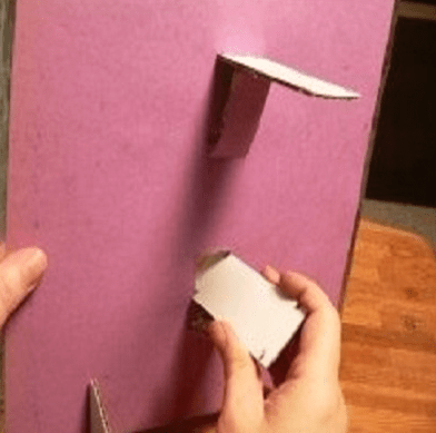
- Since you need to connect the antenna to the TV using a plug and cable, you need to cut off about 5 cm of insulation on the cable.
- Divide in half and bend the opened winding.
- Carefully cut off the inner winding and expose the cable core.
- Secure the core with winding in the plug using screws. If your plug does not have room to attach the winding, then you need to cut it off.
- Strip the other edge of the cable, make a ring from the core and secure it to the circuit.
- Wrap the joints with insulation for structural reliability.
To improve the signal on your home antenna, you need to use electronic signal amplifiers.
Powerful homemade antenna
In order for the antenna to work as well as the purchased one, or even better, you need to improve its receiving circuit.
- The first step is to buy a signal amplifier for a television antenna, which connects directly to the antenna, and be sure to wrap the cable at both ends with electrical tape so that there is no interference in the signal.
- In order for the reception to be of high quality, you need to make a screen - this is a metal mesh that is isolated from the TV and placed behind the receiver. You can use a metal mesh from a fence as a screen.
- The reception area should be increased if possible - to do this, you can attach metal rods to the screen, paying attention to the fact that the entire structure is made of the same metal, so that oxidation does not occur over time. The rods must be connected to the screen symmetrically to create the largest possible area.
- In the center of the structure you need to place another amplifier, soldering the contacts to the receiver.
Antennas for this type of TV are not installed in the house; they are usually placed on the roof, turning towards the nearest TV tower.
Antenna made from a minimum of materials
Since making an antenna for a TV at home does not always allow available tools, two completely elementary methods have become widespread:

- For the first option you will need the simplest wire. But not aluminum - it is subject to very rapid oxidation. Copper or brass wire works great. Strip the wire from both ends of the insulating material, then attach one end to the battery or pipe, and insert the opposite end into the television connector. You will notice that a signal immediately appears, since the pipe, passing through most of the house and exiting upward, is an amplifier of the desired frequencies. In this way you can “catch” about 5 channels.
- The second option will be available only to those who have a balcony. You need to take the same wire as in the first option, only longer, so that it connects the TV and the balcony area. Strip the wire on both sides, connect one end to the TV, and wind the other to the stretched strings on which the laundry is hung. Such an improvised antenna will not only help increase the number of received channels, but will also improve the image quality by an order of magnitude.
You can make not only simple, but also satellite antennas for your TV with your own hands. This is especially true for those who live far from big cities and cannot buy a parabolic receiver in a store. It is good if the TV tower is located no more than 35 km from the house so that the signal is strong enough. And if there is a tall building nearby, then the task will become even easier.

To do satellite dish for TV, you will need:
- unnecessary umbrella;
- foil;
- antenna cable (preferably made of copper);
- beer can;
- signal amplifier with power supply.
Antenna assembly instructions:
- Measure the antenna array (umbrella): measure the length between the spokes, take into account the height of the desired segment and the angle at which the spokes are attached.
- Transfer all the calculations to the foil and cut out the parts so that they fit the triangular sector of the umbrella.
- Sew the foil parts to the umbrella fabric with nylon threads - as a result, its entire internal part should be covered with foil.
- Install the signal receiver at the focus of the antenna array. You can either buy an amplifier in a store or make it yourself. In the latter case, it is enough to remove 4 cm of the outer winding from the cable, trim the screen that protects against interference and leave the core (it will transmit the signal).
- Cut an oval out of a beer can, make a hole in the center of the oval, thread a wire into it and solder a contact.
- Cover the joint with plasticine - this way the metal will not rust or oxidize.
- Attach the receiver to the handle of the umbrella using tape, tie the cables with an allowance of 10 cm - this way you can adjust the structure. It is very important to ensure that the receiver does not come into contact with the metal on the umbrella handle, otherwise interference may occur. At the point of contact, you need to stick plasticine or other insulating material.
- Attach the antenna, pointing it at the television tower, and adjust the channels by turning the umbrella in different directions. Place the power supply next to the TV, because the amplifier is powered via a cable.
We hope that experienced craftsmen will also gain some useful information from this article. And for beginners who have not yet felt the air, it is best to start with a “beer” antenna.
DIY home TV antenna was last modified: May 11th, 2016 by MaximB
Once upon a time, a good television antenna was in short supply; purchased ones did not differ in quality and durability, to put it mildly. Making an antenna for a “box” or “coffin” (an old tube TV) with your own hands was considered a sign of skill. Interest in homemade antennas continues to this day. There is nothing strange here: the conditions for TV reception have changed dramatically, and manufacturers, believing that there is and will not be anything significantly new in the theory of antennas, most often adapt electronics to long-known designs, without thinking about the fact that The main thing for any antenna is its interaction with the signal on the air.
What has changed on air?
Firstly, almost the entire volume of TV broadcasting is currently carried out in the UHF range. First of all, for economic reasons, it greatly simplifies and reduces the cost of the antenna-feeder system of transmitting stations, and, more importantly, the need for its regular maintenance by highly qualified specialists engaged in hard, harmful and dangerous work.
Second - TV transmitters now cover almost all more or less populated areas with their signal, and a developed communication network ensures the delivery of programs to the most remote corners. There, broadcasting in the habitable zone is provided by low-power, unattended transmitters.
Third, the conditions for the propagation of radio waves in cities have changed. On the UHF, industrial interference leaks in weakly, but reinforced concrete high-rise buildings are good mirrors for them, repeatedly reflecting the signal until it is completely attenuated in an area of seemingly reliable reception.
Fourth - There are a lot of TV programs on air now, dozens and hundreds. How diverse and meaningful this set is is another question, but counting on receiving 1-2-3 channels is now pointless.
Finally, digital broadcasting has developed. The DVB T2 signal is a special thing. Where it still exceeds the noise even just a little, by 1.5-2 dB, the reception is excellent, as if nothing had happened. But a little further or to the side - no, it’s cut off. “Digital” is almost insensitive to interference, but if there is a mismatch with the cable or phase distortion anywhere in the path, from the camera to the tuner, the picture can crumble into squares even with a strong clean signal.
Antenna requirements
In accordance with the new reception conditions, the basic requirements for TV antennas have also changed:
- Its parameters such as the directivity coefficient (DAC) and the protective action coefficient (PAC) are now of no decisive importance: modern air is very dirty, and along the tiny side lobe of the directional pattern (DP), at least some interference will get through, and You need to fight it using electronic means.
- In return, the antenna's own gain (GA) becomes especially important. An antenna that catches the air well, rather than looking at it through a small hole, will provide a reserve of power for the received signal, allowing the electronics to clear it of noise and interference.
- A modern television antenna, with rare exceptions, must be a range antenna, i.e. its electrical parameters must be preserved naturally, at the level of theory, and not squeezed into acceptable limits through engineering tricks.
- The TV antenna must be coordinated with the cable over its entire operating frequency range without additional devices coordination and balancing (USS).
- The amplitude-frequency response of the antenna (AFC) should be as smooth as possible. Sharp surges and dips are certainly accompanied by phase distortions.
The last 3 points are determined by the requirements for receiving digital signals. Customized, i.e. Working theoretically at the same frequency, antennas can be “stretched” in frequency, for example. antennas of the “wave channel” type on the UHF with an acceptable signal-to-noise ratio capture channels 21-40. But their coordination with the feeder requires the use of USSs, which either strongly absorb the signal (ferrite) or spoil the phase response at the edges of the range (tuned). And such an antenna, which works perfectly on analogue, will receive “digital” poorly.
In this regard, from all the great variety of antennas, this article will consider TV antennas available for self-made, the following types:
- Frequency independent (all-wave)– does not have high parameters, but is very simple and cheap, it can be done in literally an hour. Outside the city, where the airwaves are cleaner, it will be able to receive digital or a fairly powerful analogue not a short distance from the television center.
- Range log-periodic. Figuratively speaking, it can be likened to a fishing trawl, which sorts the prey during fishing. It is also quite simple, fits perfectly with the feeder throughout its entire range, and does not change its parameters at all. The technical parameters are average, so it is more suitable for a summer residence, and in the city as a room.
- Several modifications of the zigzag antenna, or Z-antennas. In the MV range, this is a very solid design that requires considerable skill and time. But on the UHF, due to the principle of geometric similarity (see below), it is so simplified and shrunk that it can well be used as a highly efficient indoor antenna under almost any reception conditions.
Note: The Z-antenna, to use the previous analogy, is a frequent flyer that scoops up everything in the water. As the air became littered, it fell out of use, but with the development of digital TV, it was once again on the high horse - throughout its entire range, it is just as perfectly coordinated and keeps the parameters as a “speech therapist.”
Precise matching and balancing of almost all antennas described below is achieved by laying the cable through the so-called. zero potential point. It has special requirements, which will be discussed in more detail below.
About vibrator antennas
In the frequency band of one analog channel, up to several dozen digital ones can be transmitted. And, as already said, the digital works with an insignificant signal-to-noise ratio. Therefore, in places very remote from the television center, where the signal of one or two channels barely reaches, the good old wave channel (AVK, wave channel antenna), from the class of vibrator antennas, can be used for receiving digital TV, so at the end we will devote a few lines and to her.
About satellite reception
There is no point in making a satellite dish yourself. You still need to buy a head and a tuner, and behind the external simplicity of the mirror lies a parabolic surface of oblique incidence, which not every industrial enterprise can produce with the required accuracy. The only thing homemade people can do is set up a satellite dish, about that.
About antenna parameters
Accurate determination of the antenna parameters mentioned above requires knowledge of higher mathematics and electrodynamics, but it is necessary to understand their meaning when starting to manufacture an antenna. Therefore, we will give somewhat rough, but still clarifying definitions (see figure on the right):

- KU - the ratio of the signal power received by the antenna on the main (main) lobe of its RP to its same power received in the same place and at the same frequency by an omnidirectional, circular, DP antenna.
- KND is the ratio of the solid angle of the entire sphere to the solid angle of the opening of the main lobe of the DN, assuming that its cross section is a circle. If the main petal has different sizes in different planes, you need to compare the area of the sphere and its cross-sectional area of the main petal.
- SCR is the ratio of the signal power received at the main lobe to the sum of the interference powers at the same frequency received by all secondary (back and side) lobes.
Notes:
- If the antenna is a band antenna, the powers are calculated at the frequency of the useful signal.
- Since there are no completely omnidirectional antennas, a half-wave linear dipole oriented in the direction of the electric field vector (according to its polarization) is taken as such. Its QU is considered equal to 1. TV programs are transmitted with horizontal polarization.
It should be remembered that CG and KNI are not necessarily interrelated. There are antennas (for example, “spy” - single-wire traveling wave antenna, ABC) with high directivity, but single or lower gain. These look into the distance as if through a diopter sight. On the other hand, there are antennas, e.g. Z-antenna, which combines low directivity with significant gain.
About the intricacies of manufacturing
All antenna elements through which useful signal currents flow (specifically, in the descriptions of individual antennas) must be connected to each other by soldering or welding. In any prefabricated unit in the open air, the electrical contact will soon be broken, and the parameters of the antenna will deteriorate sharply, up to its complete unusability.
This is especially true for points of zero potential. In them, as experts say, there is a voltage node and a current antinode, i.e. its greatest value. Current at zero voltage? Nothing surprising. Electrodynamics has moved as far from Ohm's law on direct current as the T-50 has gone from a kite.
Places with zero potential points for digital antennas are best made bent from solid metal. A small “creeping” current in welding when receiving the analogue in the picture will most likely not affect it. But, if a digital signal is received at the noise level, then the tuner may not see the signal due to the “creep”. Which, with pure current at the antinode, would give stable reception.
About cable soldering
The braid (and often the central core) of modern coaxial cables is made not of copper, but of corrosion-resistant and inexpensive alloys. They solder poorly and if you heat them for a long time, you can burn out the cable. Therefore, you need to solder the cables with a 40-W soldering iron, low-melting solder and with flux paste instead of rosin or alcohol rosin. There is no need to spare the paste; the solder immediately spreads along the veins of the braid only under a layer of boiling flux.

Types of antennas
All-wave
An all-wave (more precisely, frequency-independent, FNA) antenna is shown in Fig. It consists of two triangular metal plates, two wooden slats, and a lot of enameled copper wires. The diameter of the wire does not matter, and the distance between the ends of the wires on the slats is 20-30 mm. The gap between the plates to which the other ends of the wires are soldered is 10 mm.
Note: Instead of two metal plates, it is better to take a square of one-sided foil fiberglass with triangles cut out of copper.
The width of the antenna is equal to its height, the opening angle of the blades is 90 degrees. The cable routing diagram is shown there in Fig. The point marked in yellow is the point of quasi-zero potential. There is no need to solder the cable braid to the fabric in it; just tie it tightly, and the capacity between the braid and the fabric will be enough for matching.
The CHNA, stretched in a window 1.5 m wide, receives all meter and DCM channels from almost all directions, except for a dip of about 15 degrees in the plane of the canvas. This is its advantage in places where it is possible to receive signals from different television centers; it does not need to be rotated. Disadvantages - single gain and zero gain, therefore, in the interference zone and outside the zone of reliable reception, the CNA is not suitable.
Note : There are other types of CNA, for example. in the form of a two-turn logarithmic spiral. It is more compact than the CNA made of triangular sheets in the same frequency range, therefore it is sometimes used in technology. But in everyday life this does not provide any advantages, it is more difficult to make a spiral CNA, and it is more difficult to coordinate with a coaxial cable, so we are not considering it.
Based on the CHNA, the once very popular fan vibrator (horns, flyer, slingshot) was created, see fig. Its directivity factor and coefficient of performance are something around 1.4 with a fairly smooth frequency response and linear phase response, so it would be suitable for digital use even now. But - it works only on HF (channels 1-12), and digital broadcasting is on UHF. However, in the countryside, with an elevation of 10-12 m, it may be suitable for receiving an analogue. Mast 2 can be made of any material, but fastening strips 1 are made of a good non-wetting dielectric: fiberglass or fluoroplastic with a thickness of at least 10 mm.

Beer all-wave

The all-wave antenna made from beer cans is clearly not the fruit of the hangover hallucinations of a drunken radio amateur. This is truly a very good antenna for all reception situations, you just need to do it right. And it’s extremely simple.
Its design is based on the following phenomenon: if you increase the diameter of the arms of a conventional linear vibrator, then its operating frequency band expands, but other parameters remain unchanged. In long-distance radio communications, since the 20s, the so-called Nadenenko's dipole based on this principle. And beer cans are just the right size to serve as the arms of a vibrator on the UHF. In essence, the CHNA is a dipole, the arms of which expand indefinitely to infinity.
The simplest beer vibrator made of two cans is suitable for indoor analogue reception in the city, even without coordination with the cable, if its length is no more than 2 m, on the left in Fig. And if you assemble a vertical in-phase array from beer dipoles with a step of half a wave (on the right in the figure), match it and balance it using an amplifier from a Polish antenna (we will talk about it later), then thanks to the vertical compression of the main lobe of the pattern, such an antenna will give good CU.
The gain of the “tavern” can be further increased by adding a CPD at the same time, if a mesh screen is placed behind it at a distance equal to half the grid pitch. The beer grill is mounted on a dielectric mast; The mechanical connections between the screen and the mast are also dielectric. The rest is clear from the following. rice.

Note: the optimal number of lattice floors is 3-4. With 2, the gain in gain will be small, and more is difficult to coordinate with the cable.
Video: making a simple antenna from beer cans
"Speech therapist"
A log-periodic antenna (LPA) is a collecting line to which halves of linear dipoles (i.e., pieces of conductor a quarter of the operating wavelength) are alternately connected, the length and distance between which vary in geometric progression with an index less than 1, in the center in Fig. The line can be either configured (with a short circuit at the end opposite to the cable connection) or free. An LPA on a free (unconfigured) line is preferable for digital reception: it comes out longer, but its frequency response and phase response are smooth, and the matching with the cable does not depend on frequency, so we will focus on it.

The LPA can be manufactured for any predetermined frequency range, up to 1-2 GHz. When the operating frequency changes, its active region of 1-5 dipoles moves back and forth along the canvas. Therefore, the closer the progression indicator is to 1, and accordingly the smaller the antenna opening angle, the greater the gain it will give, but at the same time its length increases. At UHF, you can achieve 26 dB from an outdoor LPA, and 12 dB from a room LPA.
LPA can be said to be an ideal digital antenna based on its totality of qualities, so let’s look at its calculation in a little more detail. The main thing you need to know is that an increase in the progression indicator (tau in the figure) gives an increase in gain, and a decrease in the LPA opening angle (alpha) increases the directivity. A screen is not needed for the LPA; it has almost no effect on its parameters.
Calculation of digital LPA has the following features:
- They start it, for the sake of frequency reserve, with the second longest vibrator.
- Then, taking the reciprocal of the progression index, the longest dipole is calculated.
- After the shortest dipole based on the given frequency range, another one is added.
Let's explain with an example. Let's say our digital programs are in the range of 21-31 TVK, i.e. at 470-558 MHz in frequency; wavelengths, respectively, are 638-537 mm. Let’s also assume that we need to receive a weak noisy signal far from the station, so we take the maximum (0.9) progression rate and the minimum (30 degrees) opening angle. For the calculation, you will need half the opening angle, i.e. 15 degrees in our case. The opening can be further reduced, but the length of the antenna will increase exorbitantly, in cotangent terms.
We consider B2 in Fig: 638/2 = 319 mm, and the arms of the dipole will be 160 mm each, you can round up to 1 mm. The calculation will need to be carried out until you get Bn = 537/2 = 269 mm, and then calculate another dipole.
Now we consider A2 as B2/tg15 = 319/0.26795 = 1190 mm. Then, through the progression indicator, A1 and B1: A1 = A2/0.9 = 1322 mm; B1 = 319/0.9 = 354.5 = 355 mm. Next, sequentially, starting with B2 and A2, we multiply by the indicator until we reach 269 mm:
- B3 = B2*0.9 = 287 mm; A3 = A2*0.9 = 1071 mm.
- B4 = 258 mm; A4 = 964 mm.
Stop, we are already less than 269 mm. We check whether we can meet the gain requirements, although it is clear that we can’t: to get 12 dB or more, the distances between the dipoles should not exceed 0.1-0.12 wavelengths. In this case, for B1 we have A1-A2 = 1322 – 1190 = 132 mm, which is 132/638 = 0.21 wavelengths of B1. We need to “pull up” the indicator to 1, to 0.93-0.97, so we try different ones until the first difference A1-A2 is reduced by half or more. For a maximum of 26 dB, you need a distance between dipoles of 0.03-0.05 wavelengths, but not less than 2 dipole diameters, 3-10 mm at UHF.
Note: cut off the rest of the line behind the shortest dipole; it is needed only for calculations. Therefore, the actual length of the finished antenna will be only about 400 mm. If our LPA is external, this is very good: we can reduce the opening, obtaining greater directionality and protection from interference.
Video: antenna for digital TV DVB T2
About the line and the mast
The diameter of the tubes of the LPA line on the UHF is 8-15 mm; the distance between their axes is 3-4 diameters. Let’s also take into account that thin “lace” cables give such attenuation per meter on the UHF that all antenna-amplification tricks will come to naught. You need to take a good coaxial for an outdoor antenna, with a shell diameter of 6-8 mm. That is, the tubes for the line must be thin-walled, seamless. You cannot tie the cable to the line from the outside; the quality of the LPA will drop sharply.
It is necessary, of course, to attach the outer propulsion boat to the mast by the center of gravity, otherwise the small windage of the propulsion craft will turn into a huge and shaking one. But it is also impossible to connect a metal mast directly to the line: you need to provide a dielectric insert of at least 1.5 m in length. The quality of the dielectric does not play a big role here; oiled and painted wood will do.
About the Delta antenna
If the UHF LPA is consistent with the cable amplifier (see below, about Polish antennas), then the arms of a meter dipole, linear or fan-shaped, like a “slingshot”, can be attached to the line. Then we will get a universal VHF-UHF antenna of excellent quality. This solution is used in the popular Delta antenna, see fig.

Antenna “Delta”
Zigzag on air
A Z-antenna with a reflector gives the same gain and gain as the LPA, but its main lobe is more than twice as wide horizontally. This can be important in rural areas when there is TV reception from different directions. And the decimeter Z-antenna has small dimensions, which is essential for indoor reception. But its operating range is theoretically not unlimited; frequency overlap while maintaining parameters acceptable for the digital range is up to 2.7.

The design of the MV Z-antenna is shown in Fig; The cable route is highlighted in red. There in the lower left there is a more compact ring version, colloquially known as a “spider”. It clearly shows that the Z-antenna was born as a combination of a CNA with a range vibrator; There is also something of a rhombic antenna in it, which does not fit into the theme. Yes, the “spider” ring does not have to be wooden, it can be a metal hoop. "Spider" receives 1-12 MV channels; The pattern without a reflector is almost circular.
The classic zigzag works either on 1-5 or 6-12 channels, but for its manufacture you only need wooden slats, enameled copper wire with d = 0.6-1.2 mm and several scraps of foil fiberglass, so we give the dimensions in fraction for 1-5/6-12 channels: A = 3400/950 mm, B, C = 1700/450 mm, b = 100/28 mm, B = 300/100 mm. At point E there is zero potential; here you need to solder the braid to a metallized support plate. Reflector dimensions, also 1-5/6-12: A = 620/175 mm, B = 300/130 mm, D = 3200/900 mm.
The range Z-antenna with a reflector gives a gain of 12 dB, tuned to one channel - 26 dB. To build a single-channel one based on a band zigzag, you need to take the side of the square of the canvas in the middle of its width at a quarter of the wavelength and recalculate all other dimensions proportionally.
Folk Zigzag
As you can see, the MV Z-antenna is a rather complex structure. But its principle shows itself in all its glory on the UHF. The UHF Z-antenna with capacitive inserts, combining the advantages of the “classics” and the “spider”, is so easy to make that even in the USSR it earned the title of folk antenna, see fig.

Material – copper tube or aluminum sheet with a thickness of 6 mm. The side squares are solid metal or covered with mesh, or covered with a tin. In the last two cases, they need to be soldered along the circuit. The coax cannot be bent sharply, so we guide it so that it reaches the side corner, and then does not go beyond the capacitive insert (side square). At point A (zero potential point), we electrically connect the cable braid to the fabric.
Note: aluminum cannot be soldered with conventional solders and fluxes, so “folk” aluminum is suitable for outdoor installation only after sealing the electrical connections with silicone, since everything in it is screwed.
Video: example of a double triangle antenna
Wave channel

The wave channel antenna (AWC), or Udo-Yagi antenna, available for self-production, is capable of giving the highest gain, directivity factor and efficiency factor. But it can only receive digital signals on UHF on 1 or 2-3 adjacent channels, because belongs to the class of highly tuned antennas. Its parameters deteriorate sharply beyond the tuning frequency. It is recommended to use AVK under very poor reception conditions, and make a separate one for each TVK. Fortunately, this is not very difficult - AVK is simple and cheap.
The operation of the AVK is based on “raking” the electromagnetic field (EMF) of the signal to the active vibrator. Externally small, lightweight, with minimal windage, the AVK can have an effective aperture of dozens of wavelengths of the operating frequency. Directors (directors) that are shortened and therefore have capacitive impedance (impedance) direct the EMF to the active vibrator, and the reflector (reflector), elongated, with inductive impedance, throws back to it what has slipped past. Only 1 reflector is needed in an AVK, but there can be from 1 to 20 or more directors. The more there are, the higher the gain of the AVC, but the narrower its frequency band.
From interaction with the reflector and directors, the wave impedance of the active (from which the signal is taken) vibrator drops the more, the closer the antenna is tuned to the maximum gain, and coordination with the cable is lost. Therefore, the active dipole AVK is made into a loop, its initial wave impedance is not 73 Ohms, like a linear one, but 300 Ohms. At the cost of reducing it to 75 Ohms, an AVK with three directors (five-element, see the figure on the right) can be adjusted to almost a maximum gain of 26 dB. A characteristic pattern for AVK in the horizontal plane is shown in Fig. at the beginning of the article.
AVK elements are connected to the boom at points of zero potential, so the mast and boom can be anything. Propylene pipes work very well.
Calculation and adjustment of AVK for analog and digital are somewhat different. For analogue, the wave channel must be calculated at the carrier frequency of the image Fi, and for digital – at the middle of the TVC spectrum Fc. Why this is so - unfortunately, there is no room to explain here. For the 21st TVC Fi = 471.25 MHz; Fс = 474 MHz. UHF TVCs are located close to each other at 8 MHz, so their tuning frequencies for AVK are calculated simply: Fn = Fi/Fс(21 TVC) + 8(N – 21), where N is the number of the desired channel. Eg. for 39 TVCs Fi = 615.25 MHz, and Fc = 610 MHz.
In order not to write down a lot of numbers, it is convenient to express the dimensions of the AVK in fractions of the operating wavelength (it is calculated as A = 300/F, MHz). The wavelength is usually denoted by the small Greek letter lambda, but since there is no default Greek alphabet on the Internet, we will conventionally denote it by the large Russian L.
The dimensions of the digitally optimized AVK, according to the figure, are as follows:

- P = 0.52L.
- B = 0.49L.
- D1 = 0.46L.
- D2 = 0.44L.
- D3 = 0.43l.
- a = 0.18L.
- b = 0.12L.
- c = d = 0.1L.
If you don’t need a lot of gain, but reducing the size of the AVK is more important, then D2 and D3 can be removed. All vibrators are made of a tube or rod with a diameter of 30-40 mm for 1-5 TVKs, 16-20 mm for 6-12 TVKs and 10-12 mm for UHF.
AVK requires precise coordination with the cable. It is the careless execution of the matching and balancing device (MCD) that explains most of the failures of amateurs. The simplest USS for AVK is a U-loop made from the same coaxial cable. Its design is clear from Fig. on right. The distance between signal terminals 1-1 is 140 mm for 1-5 TVKs, 90 mm for 6-12 TVKs and 60 mm for UHF.
Theoretically, the length of the knee l should be half the length of the working wave, and this is what is indicated in most publications on the Internet. But the EMF in the U-loop is concentrated inside the cable filled with insulation, so it is necessary (for numbers - especially mandatory) to take into account its shortening factor. For 75-ohm coaxials it ranges from 1.41-1.51, i.e. l you need to take from 0.355 to 0.330 wavelengths, and take exactly so that the AVK is an AVK, and not a set of pieces of iron. The exact value of the shortening factor is always in the cable certificate.
Recently, the domestic industry has begun to produce reconfigurable AVK for digital, see Fig. The idea, I must say, is excellent: by moving the elements along the boom, you can fine-tune the antenna to local reception conditions. It is better, of course, for a specialist to do this - the element-by-element adjustment of the AVC is interdependent, and an amateur will certainly get confused.

About “Poles” and amplifiers
Many users have Polish antennas, which previously received analogue decently, but refuse to accept digital - they break or even disappear completely. The reason, I beg your pardon, is the obscene commercial approach to electrodynamics. Sometimes I feel ashamed for my colleagues who have concocted such a “miracle”: the frequency response and phase response resemble either a psoriasis hedgehog or a horse’s comb with broken teeth.
The only good thing about the Poles is their antenna amplifiers. Actually, they do not allow these products to die ingloriously. Belt amplifiers are, firstly, low-noise, broadband. And, more importantly, with a high-impedance input. This allows, at the same strength of the EMF signal on the air, to supply several times more power to the tuner input, which makes it possible for the electronics to “rip out” a number from very ugly noise. In addition, due to the high input impedance, the Polish amplifier is an ideal USS for any antennas: whatever you attach to the input, the output is exactly 75 Ohms without reflection or creep.
However, with a very poor signal, outside the zone of reliable reception, the Polish amplifier no longer works. Power is supplied to it via a cable, and power decoupling takes away 2-3 dB of the signal-to-noise ratio, which may not be enough for the digital signal to go right into the outback. Here you need a good TV signal amplifier with separate power supply. It will most likely be located near the tuner, and the control system for the antenna, if required, will have to be made separately.

The circuit of such an amplifier, which has shown almost 100% repeatability even when implemented by novice radio amateurs, is shown in Fig. Gain adjustment – potentiometer P1. The decoupling chokes L3 and L4 are standard purchased ones. Coils L1 and L2 are made according to the dimensions in the wiring diagram on the right. They are part of signal bandpass filters, so small deviations in their inductance are not critical.
However, the installation topology (configuration) must be observed exactly! And in the same way, a metal shield is required, separating the output circuits from the other circuit.
Where to begin?
We hope that experienced craftsmen will find some useful information in this article. And for beginners who don’t yet feel the air, it’s best to start with a beer antenna. The author of the article, by no means an amateur in this field, was quite surprised at one time: the simplest “pub” with ferrite matching, as it turned out, takes the MV no worse than the proven “slingshot”. And what it costs to do both - see the text.
(2
ratings, average: 4,00
out of 5)
And on the roof there was a satisfactory reception for Polyachka. I’m 70–80 kilometers from the television center. These are the problems I have. From the balcony you can catch 3-4 pieces from 30 channels, and then with “cubes”. Sometimes I watch TV channels from the Internet on the computer in my room, but my wife cannot watch her favorite channels normally on her TV. Neighbors advise installing cable, but you have to pay for it every month, and I already pay for the Internet, and my pension is not flexible. We keep pulling and pulling and there’s not enough for everything.
Pyotr Kopitonenko said:
It’s not possible to install an antenna on the roof of the house; the neighbors swear that I walk around and break the roofing material covering and then their ceiling leaks. Actually, I am very “grateful” to that economist who received a prize for saving money. He came up with the idea of removing the expensive gable roof from the houses and replacing it with a flat roof covered with poor roofing material. The economist received money for saving, and the people on the top floors now suffer all their lives. Water flows on their heads and on their beds. They change the roofing felt every year, but it becomes unusable within a season. In frosty weather, it cracks and rainwater and snow flow into the apartment, even if no one walks on the roof!!!
Sergey said:
Greetings!
Thanks for the article, who is the author (I don’t see the signature)?
The LPA works perfectly according to the above method, UHF channels 30 and 58. Tested in the city (reflected signal) and outside the city, distances to the transmitter (1 kW) respectively: 2 and 12 km approximately. Practice has shown that there is no urgent need for the “B1” dipole, but another dipole before the shortest one has a significant effect, judging by the signal intensity in %. Especially in city conditions, where you need to catch (in my case) the reflected signal. Only I made an antenna with a “short circuit”, it turned out that way, there was simply no suitable insulator.
In general, I recommend it.
Vasily said:
IMHO: people looking for an antenna to receive digital TV, forget about the LPA. These wide-range antennas were created in the second half of the 50s (!!) of the last century in order to catch foreign television centers while on the shores of the Soviet Baltic states. In magazines of the time, this was bashfully called “extra-long-range reception.” Well, we really loved watching Swedish porn at night on the Riga seaside...
In terms of purpose, I can say the same about “double, triple, etc. squares”, as well as any “zigzags”.
Compared to a “wave channel” of similar range and gain, LPAs are more bulky and material-intensive. Calculating the LPA is complex, intricate and more like fortune telling and adjusting the results.
If in your region ECTV is broadcast on neighboring UHF channels (mine are 37-38) then The best decision find a book online: Kapchinsky L.M. Television antennas (2nd edition, 1979) and make a “wave channel” for a group of UHF channels (if you broadcast above 21-41 channels, you will have to recalculate) described on page 67 et seq. (Fig. 39, Table 11).
If the transmitter is 15 - 30 km away, the antenna can be simplified by making it four - five element, simply without installing directors D, E and Zh.
For very close transmitters, I recommend indoor antennas; by the way, in the same book on pp. 106 – 109 there are drawings of wide-range indoor “wave channel” and LPA. The “wave channel” is visually smaller, simpler and sleeker with higher gain!
By clicking the “Add comment” button, I agree with the site.
How to make an antenna for a TV with your own hands so that it is not inferior in quality to a purchased device is a question that interests many home craftsmen and TV enthusiasts. Exist various ways How to make an antenna yourself, from the simplest designs to devices that receive satellite signals.
This option is suitable for people who want to install a regular indoor antenna at home or in the country for viewing federal channels. Anyone can construct such a device; no special knowledge is required.
This is the most basic method, so you only need copper wire 70–90 cm, thickness 2–3 mm. An indoor antenna is made as follows:
- Strip both ends of the copper wire.
- Attach one end to the battery, and insert the other into the TV connector.
The signal will appear immediately, and from 1 to 5 channels will be available to the user. So simple method you can make a home antenna in 5 minutes.
The most popular way to make an antenna with your own hands from scrap materials. To make this you will need beer cans. Experts say that it will take no more than an hour to assemble an antenna from beer cans.
You will need:
- Connecting cable.
- Several cans of beer.
- Plug.
- Screws in the amount of 2 pieces.
- Screwdrivers.
- Insulating tape or heat shrink tubing.
- A wooden beam or metal pipe for mounting the antenna.
You can make a homemade antenna from tin cans according to the following scheme:

This is another easy option on how to make a TV antenna in a short time. The device picks up the signal well, providing high image quality.
All-wave antenna with amplifier
An all-wave antenna with an amplifier can be of different configurations. Its assembly takes more time than the first two options. But the advantage is that it is very powerful and receives all analog channels in excellent quality. One of the common options is the all-wave antenna of the “BUTTERFLY” shape.
Tools:
- Board or plywood sheet, dimensions 550/70/5 mm.
- Copper wire.
- Connecting cable PC75.
- Drill.
- Soldering iron.
- Plug.

Instructions:

The DIY TV antenna is ready for use.
UHF antenna
Homemade antennas that pick up a decimeter signal can be of a variety of configurations.
Option 1
Most simple option counts it is relatively easy and simple to assemble.
You will need:
- Plywood.
- Cord.
- Soldering iron.

Instructions:
- Make a ring from the connecting cable, size 53 cm.
- Cut another piece of cable to make a loop, size 17.5 cm.
- You need to solder a loop to the ring and a cable that will be inserted into the screen.
- Attach the structure to the plywood.
- Point the assembled device towards the TV tower.
Thus, a UHF antenna is assembled with your own hands.
Option 2
Another possible method for making a TV antenna UHF band called "Eight".
Tools:
- Wire (copper, aluminum).
- Glue gun.
- Cable.
- Wire cutters.

Instructions:

This is another way you can make an antenna yourself.
This device's signal range can reach up to 490 MHz, this means that the picture quality will be very high. But for manufacturing you need to purchase a transformer.
You will need:
- Transformer.
- Foil.
- Glue.
- Roulette.
- Cardboard.
- Stapler.
- Marker.

Instructions:
The device is ready for use.
DIY satellite dish
One of the most popular questions is, is it possible to make a satellite dish with your own hands? There are many videos on the Internet on how to make a plate for viewing. satellite television on one's own.
This device can be made at home in two ways:
- Sticking on the matrix.
- Soldering mesh and wire.
The first manufacturing method is considered the most optimal and convenient. To do this, you need to make a drawing of the future device. The work must be approached very responsibly at this stage, all parameters must be calculated accurately, otherwise the output will be a device unsuitable for operation. The drawing draws a parabola, which is then transferred to a steel sheet. Its thickness should be 0.05 cm.

Stages of work
- Using a welding machine, make a steel frame with a diameter of 9–10 cm. The steel rods are turned to the outside, and the bearing is welded to the center.
- Install the resulting structure on a level place, and a pipe is attached to the installed bearing, then a knife is installed.
- Then the frame is filled with concrete and dried for 5 days.
At the final stage, it is necessary to glue the antenna, this can be done different ways. To make work easier, it is recommended divide the structure into 8 parts. For gluing, fiberglass or epoxy primer is used.
Apply machine oil to the dry concrete form and insert the pipe into the washer. Afterwards, the homemade plate is covered with resin and the fiberglass is glued. The manufacturing process of the device is completed. Read also,.