Applied science does not stand still. Thanks to this, our life becomes comfortable and safe. This is how new devices and gadgets appear in everyday life, and old ones are improved. They become compact, versatile and quickly get rid of wires. The situation is similar with doorbells. Nowadays you won’t surprise anyone with a call with a lot of melodies, good sound quality or imitating a person’s voice.
But the wireless radio call is a new product on the market. However, its popularity is only growing every day. This is due, first of all, to the fact that it is easy to install and does not require laying wires or drilling into walls. This is important when it is installed on a vestibule door or on the gate of a private house.
Wireless doorbell
So what is the secret of such a unique device. As they say, everything ingenious is simple. It is enough to look under its body to be convinced of this.
Wireless call schemes
Radio calls differ from each other in their set of functions, range or power source. They are similar in one thing - there is a receiver and a signal transmitter. The source is a button, and the receiver is a device with a music chip, antenna and speaker. Let's take a closer look at how the wireless doorbell circuit is fundamentally expressed.
 Approximate view of transmitter microcircuits
 As can be seen in the diagram, the transmitter consists of a high-frequency generator, an amplifier-converter, three transistors and a power source. A 12 volt battery is used as a power source. The signal transmission frequency to the receiver is 433 MHz. There is no antenna as such here. It consists of two circuits that are connected in parallel. Thus, a simple microcircuit allows you to transmit a signal over 50 meters or more.
 General view of the receiver chips
 The receiver device is quite simple. It is based on one transistor. From the transmitter the signal goes to the detector. He receives it and sends it to the amplifier. The signal is then sent to the sound chip. The future signal that a person will hear is generated on this chip. Also thanks to him, they change the melodies, choose the sound volume, and so on. After the signal reaches the chip, it goes to the audio amplifier and then to the speaker.
Most Chinese-made call transmitter and receiver microcircuits are designed according to this principle.
For comparison, consider the circuits of Chinese wired doorbells. The main difference is the presence of antennas and the method of transmitting the signal from the transmitter to the receiver.
 Wired Chinese call diagram
 Homemade wireless bell
Let's consider one of the homemade microcircuits of a wireless analogue of such a device. In the basic principle of operation they are similar, but there are some differences. The main difference is the frequency at which the signal is transmitted from the transmitter to the receiving device - 87.9 MHz. The device itself consists of the following main modules:
- Control circuits,
- sound chip,
- transmitter,
- Power supply.
Let's look at each element of the circuit in more detail.
 Diagram of a homemade radio doorbell.
 The device is controlled using the S1 button. Essentially, it starts the music chip and timer of the transmitter. When it is pressed, voltage flows to pins 6 and 13. There is also a microcircuit with resistor R2 and two diodes VD1 and VD2. It limits the upper voltage value on pins 6 and 13. This is necessary since the USM and K561 microcircuits differ in their logical level. The control device itself is based on the D1 chip. It plays the role of a timer that turns on the transmitter for a few seconds after the S1 button is pressed.
Single positive pulses are generated through elements D1.1 and D1.2. Their duration is directly related to the time constant in the C1-R4 circuit (taking into account the values indicated in the diagram, we can say that the duration of the pulses is about twenty seconds). The pulse changes polarity, hitting the inverter D1.3, and then goes to the VT1 switch. The power source is transformerless, and the installed capacitor C5 dampens excess voltage.
Important! In this circuit, polar capacitors are used of the electrolytic type, C11 and C12 are ceramic, and the rest are of any kind. It is necessary that all capacitors have a voltage of at least 16V, and for C5 - at least 300V. Coils L1 and L2 are wrapped with thin wire: the first - 6 turns, the second - two. Both are frameless and have an internal diameter of seven millimeters.
The UMS8-08 microcircuit is used for the sound chip. It reproduces 8 different sounds embedded in it. The selection of melodies is carried out by flipping through S1. If you send the output pulses from the D2 chip through the transistor switch VT2 to the transformer T1 with capacitor C10, and then to the speaker, the sound of the signal will be soft and pleasant to the ear (high and harsh sounds will disappear).
A piece of wire is used as an antenna. A length of no more than a meter will be sufficient. With such an antenna, the device transmits a signal from the transmitter to the receiver over a distance of up to one hundred meters.
Now you need to configure the device. The first step is to check the power source. Next, check that the sound chip is working correctly. If everything works, then proceed to setting up the transmitter. For a while, the wiring closes VT1 and the emitter. The receiver itself is installed at the frequency indicated above. Using settings C11 and C12, we achieve reliable reception at maximum range. Thanks to resistor R8, we set modulation for better sounding of the receiver. Then the jumper is removed and the timer is set on D1. To do this, briefly press button S1. In this case, the transmitting device turns on and operates for several seconds. If this time period is too small or, conversely, too long, then it is changed by selecting R4 and C1.
Thus, having minimal knowledge and purchasing everything you need at the nearest radio store, you can make a reliable call yourself.
Ringing from unnecessary devices
If you have old phone or a broken computer mouse and their repair is impractical, then they will come in handy if you decide to make your own wireless doorbell. Consider the option of making a similar device from a mouse:
- All internals are removed from the case except the contact buttons.
- On the board, two keys are connected to the bell device, and the remaining parts are removed.
- The wheel is cut in half and one part is glued back.
- On the remote control board, a twisted pair is soldered to the sound button. It connects the button to the mouse keys.
- Solder the remaining ends to the key contacts - one to the outermost one, the second to any of the remaining two.
- The last contact of the three is connected by a wire to the opposite one. This way both buttons will work.
The original call is ready.
In contact with
Comments
Vladimir 03/28/2017 21:44
Cheap and effective. We need to adopt it!
Grade
New articles
New comments
ArtemGrade
ElenaGrade
nezabudka-1Grade
CatherineGrade
VladimirGrade
Latest reviews
adminadminIn order to arrange convenient access to the apartment, you should understand the doorbell diagram. Today there are many models of such devices, but the general principle of their operation remains almost the same. Let's look at how to properly install and repair a bell if necessary.
Depending on the type of doorbell, the connection method may differ significantly
Device Features
In each house, a whole list of additional devices is installed at the entrance to create comfortable conditions. One of them is the doorbell. Its direct purpose is to notify people in the apartment that guests have come to them.
Every person is superficially familiar with the bell device. A call button is attached to the outside of the home; a speaker is installed inside the apartment, which picks up the signal from the button and transmits it in the form of a sound alert. This is how the simplest models work. IN modern devices functions are significantly expanded up to the transfer of video images online to Cell phones. Depending on personal preferences, the available budget and the requirements of the owners, you choose how to make a doorbell: in the form of a simple addition or with all the available auxiliary capabilities.
Very often, home owners plan to install a doorbell with their own hands, so it is important to understand the circuit diagram and connection method. To do this, first of all, you should consider the main models existing on the modern market.

A modern doorbell with a video peephole will ensure home security
Types of calls
Today, the range of products in this group is huge and does not stop expanding. With the development of technology, not only the external characteristics of calls are improving, but also their functionality.
Installation of a doorbell can now be done in a matter of minutes, since manufacturers have previously provided for the lightweightness of the device and ease of use.
There are the following types of doorbells:
- Wired. This scheme is already becoming obsolete. All elements are connected to each other by cable, which somewhat complicates the connection process. The instructions should include a diagram to assist with installation.
- Wireless. Instead of a cord, a circuit is used to transmit a radio signal and receive it through an antenna. The only wire may be the power supply cable.
- Sound. The signal is a sound notification: a call, a melody, a musical composition, a voice recording.
- Video calls. Connecting a doorbell with a video camera allows you to see what is happening behind the door. Some models are activated only when you press a button, while others can turn on based on a motion sensor or continuously broadcast a picture.
- Intercoms. Allows you to transmit voice messages both inside the house and outside. Can be combined with a video system.

Types of doorbells depending on the principle of operation
Connection rules
Connecting the device is carried out in several stages, but before installing the doorbell, you need to carefully consider its location. Please note that the sound of the signal should be clearly audible in all rooms, this is especially true for private homes. Some models can be equipped with multiple speakers that can be placed in different parts of the house. And if there are several inputs, you can purchase an additional call button.
So, how to connect a doorbell:
- Wireless. The wiring diagram for such a do-it-yourself doorbell is the simplest. To begin, install the call button in a convenient location. Then determine where to hang the speaker, taking into account the range of the device and possible obstacles to the signal. The elements are attached with bolts or adhesive tape.
- Wired. Here you need to figure out in advance exactly how to connect the doorbell. Please note that you will have to run a wire connecting both devices, so think about the optimal path in advance. It is advisable to disguise it in the wall, under a suspended ceiling or baseboard. A wire goes from the button to the speaker, and from there to an outlet or directly to the power supply. For work safety, first turn off the voltage in the distribution panel. The connection principle itself is as follows: first, the wires for connecting the device (phase and neutral) are brought out, the supply wire is inserted into the housing of the bell speaker and secured to the terminals. The second part is connected to the call button, power is supplied to the bell and its operation is checked.
- Video calls. The main difference is the additional placement of a camera above the door and a screen for receiving images.

Connection diagrams for various types of doorbells
Repair
If certain problems arise after installation or during operation, you need to know how to fix the doorbell yourself. Most often, the cause of failures is contact separation. To fix the problem, you need to look at the locations of the key connections. This could be a button or a speaker inside the house. Sometimes it is enough to tug the wires and the call works normally again. It is much worse if the leading cable is broken. Then it needs to be replaced or soldered.

If you use the doorbell for a long time, problems with the contacts may occur.
There may also be problems with nutrition. Then you need to check and repair the power supply and input plugs yourself. IN wireless models Do not forget to change batteries on time and monitor the condition of the battery.
This issue is especially relevant for outdoor devices in areas with a cold climate and sudden temperature changes.
If you understand the bell device, you won’t have any problems installing it yourself. In addition, if problems arise, you can easily fix it without requiring outside help.
A doorbell is a very convenient device. All apartments and houses are equipped with it, with very rare exceptions. When choosing this device, you need to know what types of connections exist and how to connect them correctly.
Types and types of devices
Depending on the connection method, doorbells are divided into two types:
Wired products on the door operate both from electricity and from an autonomous power source. The button and soundbar of such devices must be connected to each other using wires. Wireless ones do not require physical connection of elements.
According to the type of mechanism, calls are:
- hammer;
- buzzer;
- bell.

They differ from each other in internal structure and operating principle. But they can work both from the mains and from a battery.
What to pay attention to
When choosing a doorbell, it is better to give preference to a device that has the ability to adjust the volume. Another one useful feature– this is the backlight of the button in the dark. It is implemented using a small LED, or luminous materials. Concerning appearance housing and sound, there are many options on offer here. Everything will depend only on your tastes and preferences.

The choice of electrical product depends on whether you will install it in an apartment or a house. They can be two or four wire. The 2-wire button is supplied with 220V voltage, and the 4-wire button is supplied with 5V. Both types can be installed in an apartment. And in a house where the button and wire are exposed to weather conditions (rain, snow, high humidity), only 4-wire devices are installed.
The electric wired bell operates from the network. This is both a plus and a minus. On the one hand, you do not need to constantly monitor the battery charge, as in wireless devices. On the other hand, the device will not function if there is no light. Another minus - dangerous current, so it is important to be extremely careful when installing.
Connection Tools
Connecting a doorbell yourself is not at all difficult. You just need to know how to do it and have the necessary tools.

- drill, dowels;
- construction knife, electrical tape;
- indicator screwdriver;
- self-tapping screws
Wiring and connection diagram
The operation of an electric bell is not possible without electricity. Therefore, wiring must be connected to the place where the device will be attached. As a rule, wired products operate from the network alternating current with voltage 220v. You can use one two-core cable or two single-core cables. The wire cross-section can be 0.5 square millimeters or more. However, it is not necessary to use thicker wires, since the power consumed by a wired bell is small. The only thing to consider is their material. It must be the same as that used for wiring throughout the entire house or apartment.
The connection diagram for different products is different. As a rule, in all new buildings during construction, wiring is installed for a standard door device. If you are engaged in construction yourself or connecting a wired electric bell is not provided for some reason, then you can choose a product with any possible connection diagram, laying wiring to it.

The standard doorbell connection circuit exactly copies the circuit of an ordinary switch, and, as you know, it is the simplest among all available electrical diagrams. Only instead of a light bulb, a sound mechanism is used, and instead of a switch, a button is used. Zero connects to soundbar, and the phase – to the button. Moreover, both elements are also connected to each other. When you press the button, the phase is closed and a sound signal is heard.
Installation of the sound mechanism
If all the wires in the apartment are already laid, then installing a doorbell will not take much time. The device operates on current, so you must follow safety rules when working with electrical devices. The electrical product is connected only after the power has been turned off in the entire apartment.

The doorbell is connected to the current by connecting its contacts to the apartment wiring. If they are too long, they need to be trimmed and cleaned with a construction knife. Electricians recommend lightly squeezing the already connected wires with pliers so that the connection is more reliable and the contact is better. We isolate the connections and check that everything works. If a four-wire mechanism is connected to two-wire wiring, then the phase and zero that will participate in the connection are determined. The remaining wires are connected to each other and carefully insulated.
If the wired bell works successfully, then it’s time to start attaching it to the wall.
The installation location is usually in the corridor or hallway. At the same time, there should be no radiators or other heating devices within a radius of one and a half meters from the device. At the installation site in the wall, a hole is made with a drill and the sound mechanism panel is attached using dowels and screws. Hidden mounting holes are provided by all device manufacturers. A hole is drilled in the door frame to connect the wires between the sound panel and the button.
Installing a button
The bell button consists of two contacts, one of which is spring-loaded. When you press it, it touches the second one, the chain closes and the mechanism rings. When released, the contacts open.

To install the button, two wires must be supplied, which must be connected to its two contacts. The connections are well wrapped with electrical tape or securely fastened with terminals, depending on how it is provided in your device. And the button itself is attached to the wall using a wooden panel.
Wired call with two buttons
It is not uncommon to encounter a situation when you need to connect two buttons to one call. This is necessary, for example, when there is one common vestibule for several apartments. In this case, one is placed in the vestibule, and the second on the platform in front of the door. The device connection diagram will then have two parallel buttons. When you press any of them, the circuit will close and the mechanism will work.

It is quite possible to connect a doorbell yourself. The whole procedure will take no more than half an hour, provided there is wiring.
A wireless doorbell does not need to be connected, as the signal is transmitted by radio waves - this is the main advantage over wired devices. This type of call is preferred by private homeowners when the wire to the gate is pulled underground (labor-intensive and expensive) or in the air (the cable is not protected from precipitation). And if you approach the installation creatively, you can surprise your friends.
To install a wired doorbell with your own hands, a connection diagram is required: this is a manual, the reading of which requires special knowledge. And with the wireless analogue there is no hassle. In the box with the purchased device you will find a button and a music unit (bell box). Additionally you will need:
- Dowel-nails with self-tapping screws and a hammer drill, if you install the button on a concrete wall. The hammer drill can be replaced with an impact drill;
- Self-tapping screws if the base is wooden;
- Batteries. Immediately insert them into the button and bell housing.
If you are installing a button on a concrete wall in a place where a wired bell is connected, first insulate the two-core or three-core cable coming out of the wall. But only after turning off the power to the apartment! Then drill a hole to insert the dowel nail. Leaning the key down, secure it with a self-tapping screw.
If the button is on a wooden surface, then only self-tapping screws will be needed. But it is not recommended to install it on metal, since it can interfere with the radio signal sent from the button to the bell.
Attention! Instead of complex fastening with a hammer drill and self-tapping screws, you can use double-sided tape. Just stick a piece on the back of the button housing and lean it against the wall. But such fastening is unreliable, and the button can be torn off by anyone passing by. Over time, the tape dries out and loses its fixing functions.
The ringing box is installed in any convenient place in the house. You can attach the case with double-sided tape - this is not a problem in an apartment. And if the house is constantly shaking from active children, then place the music box on double-sided tape. For those who don’t want to do anything at all, there is an excellent solution - just put the call in a place where it won’t interfere. On a shelf in the hallway, in a wardrobe, on a windowsill. The main thing is to maintain the maximum allowable distance between the radio button and the bell.
Advice! If your wireless bell is not powered by batteries, but is equipped with a plug, then simply plug it into an available outlet.
DIY mouse bell
How to make a doorbell with your own hands so that it can surprise guests? An unusual solution - a key placed in a housing from computer mouse. To build it you will need:
- Unnecessary mouse;
- A button smaller in size than a mouse;
- Small diode;
- Soldering iron;
- Pieces of cable.
 First, empty the mouse of all the insides, leaving the contact buttons.


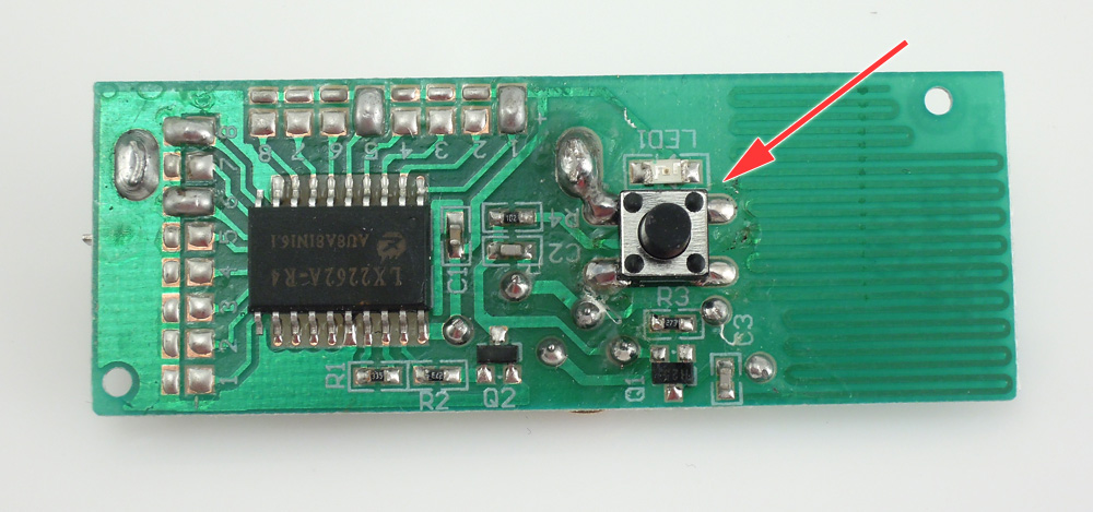
 Connect two keys on the board to the bell remote control. Remove the remaining parts so that the bell control board can be easily inserted inside. Cut the mouse wheel in half: place one half in its place using glue. Then take the remote control board, it looks like the picture below.
 The arrow on the board shows the bell button. Using a soldering iron, you need to attach a piece of twisted pair here. This is needed to connect to mouse buttons.
 On the board, the button has 4 contacts, although only 2 are working, which are connected in pairs. Solder the ends of the twisted pair to the two contacts. If the ends touch when the mouse button is pressed, a bell will sound.
 Solder the remaining ends of the twisted pair to the mouse keys. You will find three contacts, which are labeled A, B and C in the figure.
 Solder one end of the twisted pair to any contact A. The second end - either to B or C. And connect the contacts B and C themselves to each other with a piece of wire. This is necessary so that the bell is triggered when any mouse button is pressed, and not just the right or left one.
 The button can be considered working, but for beauty, you can install an LED in the place where the wire was connected to the mouse. The lamp will light up when pressed. The connection is made through a resistor. The diagram of a wireless bell with a diode is shown in the figure below.
A two door bell with indicator is well suited for use in a home where there are two gates or doors that are located far apart. It helps a person inside the house by using different sounds and number indication to determine which doors the visitor is standing near. This saves time and effort by not having to check both doors. On the site electroschematics.com I found this very interesting circuit for a homemade doorbell that functions in such a way that a different sound signal is played, depending on which button SW1 or SW2 is pressed. This is necessary for those who have 2 doors that can be called. With such a call, it is immediately clear which one is being called.

The alarm will only be activated for 1 second and the display will turn on for 1 minute and then turn off automatically to save energy. When powered by 220 V, this is not critical, but for a battery-powered bell it is very useful. The backup power supply is not shown in the diagram - you can adapt it yourself. Simply remove the transformer along with the diodes and filter capacitors and replace it with a 9-volt battery.
Electronic doorbell circuit

Schematic Parts List
- Battery or 220V/6V transformer
- D1, D2, D3, D4 - 1N4001
- C1 - 4700 uF
- C2 - 470 uF
- LM7805
- IC1, IC2, IC3 - LM555 or NE555N
- IC4 - 74LS02
- IC5 - 74LS47
- T1, T2, T3 - 2N3904
- R1, R3, R5, R7, R8, R10 - 1K
- R2, R4 - 10K
- R6 — 100k
- R9 - 600K
- 11 to R17 - 330 ohm
- R18 — 100k
- R19 – 5k
- C3 - 100 uF
- C4, C6, C8 - 0.01 uF
- C5, C7 - 10 µF
- C9 - 100 uF
- 7-segment display with common anode
- Piezo emitter
The circuit consists of mono- and astable multivibrators. You can change the frequency of the signal reproduced by the self-oscillating multivibrator by turning potentiometer R18. The call volume is affected by the resistance of resistor R19. The power consumption of the circuit is 0.2 watts. Current consumption during a call is 50 mA. Printed circuit board was not developed - everything was assembled on a breadboard.