Breakdowns and malfunctions in the operation of a computer are an integral part of the operation of the device. Breakdowns (damage) can be software and hardware. Software problems are related directly to the software, while hardware problems imply a breakdown of physical components computer system. Both groups of breakdowns require immediate and competent intervention of a specialist.
A computer power supply (or Power Supply) is a secondary element of a computer system that is necessary to fill the computer nodes with a direct current energy flow. In simple terms, Power Supply is the source of electrical power for the computer.
The need to connect PS without auxiliary elements arises in such cases:
- The need to diagnose the operation of the device.
- In the process of renovation.
- When using multiple power supplies in one computer case.
- Diagnosing the performance of new circuits.
Power Supply. General information. Standard start power supply
Using an electrical power supply helps protect your computer from frequent power outages. An obligatory element that is attached to the Power Supply is a fan (other names: cooler, cooler). It performs constant cooling of PS, protects it from overheating, which can lead to breakage.
The standard process of turning on Power Supply involves pressing the "Start" button on the motherboard, which activates the process of powering the unit. There is a widespread belief that turning on the power supply without motherboard impossible, because it does not start without voltage, but this is just a delusion.

If when you press the power button on the computer, it does not turn on and does not react in any way, then it can be assumed that, most likely, the motherboard has failed or the Power Supply has broken. Before buying new expensive components, you should diagnose the operation of existing ones.
How to turn on the power supply without a computer
To turn on the power supply without a computer, you should pay attention to the tables of the locations of all the necessary pins on the connector. The pins of a standard ATX block are shown in the table below:
| Colour | Signal | Contact | Contact | Signal | Colour |
| Orange | +3.3V | 1 | 13 | +3.3V | Orange |
| +3.3V sense | Brown | ||||
| Orange | +3.3V | 2 | 14 | -12V | Blue |
| The black | Earth | 3 | 15 | Earth | The black |
| Red | +5V | 4 | 16 | Power on | Green |
| The black | Earth | 5 | 17 | Earth | The black |
| Red | +5V | 6 | 18 | Earth | The black |
| The black | Earth | 7 | 19 | Earth | The black |
| Gray | power good | 8 | 20 | -5V | White |
| Purple | +5 VSB | 9 | 21 | +5V | Red |
| Yellow | +12V | 10 | 22 | +5V | Red |
| Yellow | +12V | 11 | 23 | +5V | Red |
| Orange | +3.3V | 12 | 24 | Earth | The black |
- The three shaded pins (8, 13 and 16) are control signals, not power.
- "Power On" is pulled up by the resistor to +5 volts inside the power supply, and must be low to turn on the power.
- "Power good" is held low until the other outputs have reached the desired voltage level.
- The "+3.3V sence" wire is used for remote sensing.
Before you learn how to turn on the power supply without a computer, follow these tips: do not start the PSU without applying at least some load. The circuit that converts electricity may break and then the ATX block will need to be replaced. Such repairs can be quite costly.
How to run a power supply without a motherboard:
- Close the Power On contact to zero. In almost all cases, it is colored green.
- Short to ground - any contact colored black. Enough to close just one. Closed contacts look like this:

- If you are using a pin chart, then take the simplest paperclip and touch it to pins 15 and 16. So in a simple way you close them. The table above will help you navigate the contacts of the ATX PSU. After the desired contacts have been closed, Power Supply should start. If this does not happen, then you can close the green wire and the other black one.
- Try your best not to overload the Power Supply. Connect to it, for example, HDD or disk drive.
Chinese block manufacturers very often confuse the English names for the colors gray (gray) and green (green), so the green wire may be gray. In any case, try to navigate the table.
Replacement of the ATX PSU is expected in the event of a breakdown of the old copy or in the event that the constituent elements of the personal computer were replaced: more powerful video cards, processors, motherboards, more random access memory. In the case of such a PC upgrade, the power supply becomes unable to supply power to all components of the PC. First of all, you need to remove the existing ATX element, install a new one and test its performance. You just need to know basic concepts schematics and follow the instructions below:
- Necessary improvised tools: standard size Phillips screwdriver.
- It is necessary to de-energize the personal computer - this process involves pulling out the power cord from the PSU.
- The next step is to remove the wall. system block, usually it is removed from the left side of the case by unscrewing a few screws.
- Remove any accumulated dust from the computer components with a brush or vacuum cleaner. Please note that cleaning the computer from accumulated dust should be done at least once every six months.. Only after complete cleaning of dust, you can proceed to the next steps.

- Disconnect all wires belonging to the PSU from other devices. Pay attention to possible presence special latches in the connectors. Do not pull out the connected wires abruptly.
- After disconnecting all the wires, unscrew the screws that attach the PSU to the computer's system PSU. Thus, the old power supply will be removed.
- To connect a new power supply unit, repeat all the steps exactly the opposite: fix it to the system unit, carefully connect all its wires to the necessary elements, connect a 220-volt power cord to the power supply unit.
AT modern world The development and obsolescence of personal computer components is very fast. At the same time, one of the main components of a PC - the ATX form factor - is practically has not changed its design for the last 15 years.
Consequently, the power supply and ultra-modern gaming computer, and an old office PC work on the same principle, have common troubleshooting techniques.
The material presented in this article can be applied to any personal computer power supply with a minimum of nuances.
A typical ATX power supply circuit is shown in the figure. Structurally, it is a classic pulse unit on a TL494 PWM controller, triggered by a PS-ON (Power Switch On) signal from the motherboard. The rest of the time, until the PS-ON pin is pulled up to ground, only the Standby Supply is active with +5 V at the output.
Consider the structure of the ATX power supply in more detail. Its first element is
:

Its mission is to transform alternating current from the mains to DC to power the PWM controller and standby power supply. Structurally, it consists of the following elements:
- Fuse F1 protects the wiring and the power supply itself from overload in the event of a PSU failure, leading to a sharp increase in current consumption and, as a result, to a critical increase in temperature that can lead to a fire.
- A protective thermistor is installed in the "neutral" circuit, which reduces the current surge when the PSU is connected to the network.
- Next, a noise filter is installed, consisting of several chokes ( L1, L2), capacitors ( C1, C2, C3, C4) and a choke with counter winding Tr1. The need for such a filter is due to the significant level of interference that the pulse unit transmits to the power network - this interference is not only picked up by television and radio receivers, but in some cases can lead to malfunctioning of sensitive equipment.
- A diode bridge is installed behind the filter, which converts alternating current into a pulsating direct current. The ripples are smoothed out by a capacitive-inductive filter.

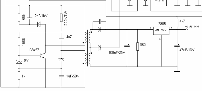
Standby power supply- This is a low-power independent pulse converter based on the T11 transistor, which generates pulses, through an isolation transformer and a half-wave rectifier on the D24 diode, feeding a low-power integrated voltage regulator on the 7805 chip. Although this circuit is, as they say, time-tested, its significant drawback is high voltage drop across the 7805 stabilizer, leading to overheating under heavy load. For this reason, damage in circuits powered from a standby source can lead to its failure and subsequent inability to turn on the computer.
The basis of the pulse converter is PWM controller. This abbreviation has already been mentioned several times, but not deciphered. PWM is pulse-width modulation, that is, changing the duration of voltage pulses at their constant amplitude and frequency. The task of the PWM unit, based on a specialized TL494 microcircuit or its functional analogues, is to convert a constant voltage into pulses of the appropriate frequency, which, after an isolation transformer, are smoothed out by output filters. Voltage stabilization at the output of the pulse converter is carried out by adjusting the duration of the pulses generated by the PWM controller.
All modern computers use ATX power supplies. Previously, AT standard power supplies were used, they did not have the ability to remotely start a computer and some circuitry solutions. The introduction of the new standard was also associated with the release of new motherboards. Computer technology rapidly developed and is developing, so there was a need to improve and expand motherboards. This standard has been introduced since 2001.
Let's see how it works computer block ATX power supply.

Location of elements on the board
To begin with, take a look at the picture, all the nodes of the power supply are signed on it, then we will briefly consider their purpose.


And here is the electrical circuit diagram, divided into blocks.

At the input of the power supply there is an electromagnetic interference filter from the inductor and capacitance (1 block). In cheap power supplies, it may not be. The filter is needed to suppress interference in the power supply network resulting from operation.
All switching power supplies can degrade the parameters of the power supply network, unwanted interference and harmonics appear in it, which interfere with the operation of radio transmitting devices and other things. Therefore, the presence of an input filter is highly desirable, but comrades from China do not think so, so they save on everything. Below you see a power supply without an input choke.

Further, the mains voltage is supplied to, through a fuse and a thermistor (NTC), the latter is needed to charge the filter capacitors. After the diode bridge, another filter is installed, usually a pair of large ones, be careful, there is a lot of voltage on their terminals. Even if the power supply is turned off from the network, you must first discharge them with a resistor or an incandescent lamp before touching the board with your hands.
After the smoothing filter, the voltage is supplied to the switching power supply circuit; it is complicated at first glance, but there is nothing superfluous in it. First of all, the standby voltage source (block 2) is powered, it can be performed according to a self-generator circuit, or maybe on a PWM controller. Usually - a circuit of a pulse converter on one transistor (single-cycle converter), at the output, after the transformer, a linear voltage converter (KRENka) is installed.

A typical circuit with a PWM controller looks something like this:

Here is an enlarged version of the cascade circuit from the example above. The transistor is in a self-oscillating circuit, the frequency of which depends on the transformer and capacitors in its piping, the output voltage from the nominal value of the zener diode (in our case 9V) which plays the role of a feedback or threshold element that shunts the base of the transistor when a certain voltage is reached. It is additionally stabilized to a level of 5V by a series-type linear integrated regulator L7805.
The standby voltage is needed not only to generate the enable signal (PS_ON), but also to power the PWM controller (block 3). ATX computer power supplies are most often built on the TL494 chip or its analogues. This block is responsible for controlling power transistors (block 4), voltage stabilization (using feedback), short circuit protection. In general, 494 is used very often in impulse technology, it can also be found in powerful power supplies for LED strips. Here is her pinout.

If you plan to use a computer power supply, for example, to power led strip, it will be better if you load the 5V and 3.3V lines a little.
Conclusion
ATX power supplies are great for powering ham radio designs and as a power source for the home lab. They are quite powerful (from 250, and modern ones from 350W), while they can be found on the secondary market for a penny, old AT models are also suitable, to start them you just need to close two wires that used to go to the system unit button, the PS_On signal to they are not.
If you are going to repair or restore such equipment, do not forget about the rules safe work with electricity, that there is mains voltage on the board and the capacitors can remain charged for a long time.
Turn on unknown power supplies through a light bulb so as not to damage the wiring and PCB tracks. If you have basic knowledge of electronics, they can be converted into a powerful charger for car batteries or. To do this, the feedback circuits are changed, the standby voltage source and the block start circuits are being finalized.
There are times in life when you need turn on the power supply without connecting it to the motherboard. There are several reasons for this inclusion. For example, check the power supply for operability or find out the noise level of its cooler.
Now all power supplies are ATX standard. Such blocks have several “pigtails” with SATA and Molex connectors for connecting drives, several connectors for supplying power to the video card, 4-pin or 8-pin processor power, and 24-pin (possibly 20-pin) motherboard power.

In addition, there is a latch key on the connector for connecting to the motherboard. So next to it is a black wire, with a hexagonal contact. If you turn the cable with the locking key down and count the fifth contact from right to left (it can be signed as COM or GND), then this will be it. Near this COM pin is a green wire, in the same row. This is the only wire and can be called PS-ON on the cable. If in doubt, turn the cable down again with the locking key and count the fourth contact from right to left.
This method of finding the desired contact is universal and does not depend on the number of contacts on the loop. Be it 24-pin or 20-pin. By the way, there are power cables with detachable 4-pin. They are also labeled 20 + 4-pin.
It may be that you have a Chinese power supply of an unknown manufacturer and there is no green wire. Do not worry. The order of the wires does not change from this.

Now we need to take a small piece of wire or paper clip, bare its edges. One end is connected to the fourth pin and the other to the fifth pin. Although you can connect another contact to any of those that have a black wire. For example, to the third pin-contact.

Now you can turn on the power supply by connecting it to the network. The power supply will work immediately. You will know it by the rotation of his cooler. If the power supply has a controlled cooling system, in which the cooler does not rotate at low loads, then try connecting the cooler from the system unit or optical drive. This will also help make sure that the power supply is working.
How to turn on a computer power supply without a computer?
Work in this mode can be no more than 5 minutes. After all, this mode of operation, without load, should be short. So before turning on the network, still connect either a cooler or a disk drive, or a hard drive. Check what worries you and turn it off. Read more interesting tips in the section
When working with a stationary PC, a situation may arise in which the computer simply refuses to turn on. Activating the "Power" button does nothing, and what can cause such a dysfunction is also unknown. Most often, suspicion falls on the computer's power supply, when it fails, the voltage to the motherboard stops. How to turn on the power supply without a computer and using the "Power" button on the case? Let's figure it out.
Features of turning on the power supply without a PC
As you know, turning on the computer is done using the "Power" button, which, in turn, is connected to the motherboard. To start the power supply without a computer, we need to exclude the motherboard from this circuit using the method that I will describe below.
When performing this operation, remember that:
- It is necessary to turn off the PC and completely disconnect the PSU from the computer;
- It is necessary to connect some kind of load to one of the external connectors of the PSU (any old hard drive or CD (DVD) disc player will do). Without such a load, various negative consequences are possible, in the form of a PSU refusal to start, its failure, and other undesirable dysfunctions;
- Be extremely careful when performing the following operations. Accidentally shorting the wrong contacts can damage the device.
We start the power supply without a computer
To bypass the circuit using the motherboard, we need some kind of metal clip or a small wire with stripped ends. Even ordinary technical tweezers may come in handy.


The green contact in the diagram is usually depicted as "PS-ON" ("Power Supply ON" - turning on the PSU), and the black one as "COM" ("Common" - common) or GND ("Ground" - ground);

Connector diagram
- The power supply should turn on, and its cooler should start working.
Some craftsmen connect a full-fledged switch instead of such wiring.

Other ways to check the PSU
There are also a number alternative ways check the functionality of the power supply.
Output voltage measurement
To check the performance of the power supply, we can measure its output voltage with a voltmeter. To do this, it is recommended to turn on the power supply as mentioned above (if it turns on). And measure the performance of a number of wires of the black and pink wires of the main 24-pin connector. In the case of black and pink wires, the indicator should be 3.3, black and yellow - 12, and black and red - 5 V. The permissible deviation should not exceed 5% up or down.

Capacitor swelling test
The second way is to check the filling of your power supply for the presence of swollen capacitors on the board. To do this, disconnect the PSU from the PC, remove the cover from it and visually inspect all available capacitors.

If you notice swollen capacitors, then there is a high probability that they have already exhausted their resource and need to be replaced. You need to unsolder them from your PSU, and replace them with new ones of the same rating.
Conclusion
To turn on the power supply without a computer, you must use a piece of wire stripped from both ends, which close the 4th and 5th contact of the main PSU connector, as described just above. Usually this method is universal, and makes it possible to understand the overall performance of this device. If the unit does not turn on, then it is quite possible that it needs a thorough repair.